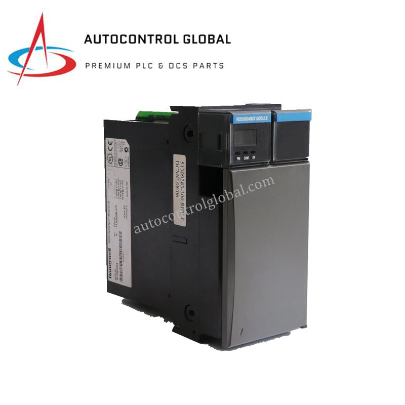
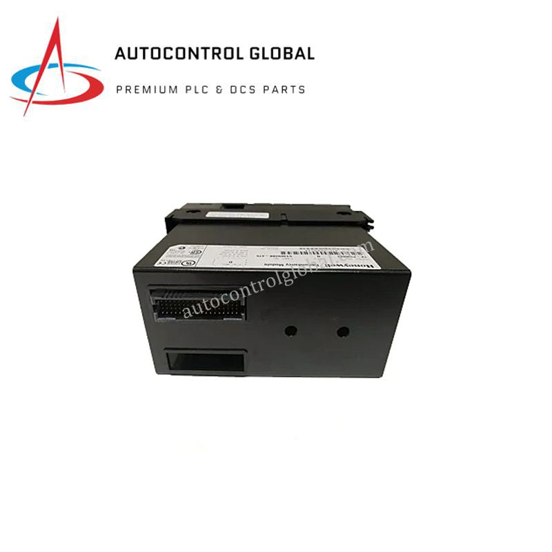
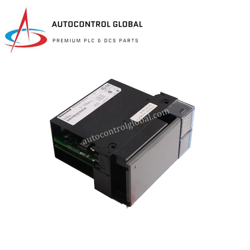


TK-PRR021 Honeywell C200 Controller Series Redundancy Module
Manufacturer: Honeywell
-
Part Number: TK-PRR021 51309288-275
Condition:New with Original Package
Product Type: Redundancy Modules
-
Country of Origin: USA
Payment:T/T, Western Union
Shipping port: Xiamen
Warranty: 12 months
Honeywell TK-PRR021 C200 Controller Series Redundancy Module
The Honeywell TK-PRR021, also cataloged as the 51309288-275 Redundancy Module, operates as a dedicated hardware component for 1+1 hot standby redundancy within Honeywell C200 Controller platforms. The module manages continuous memory synchronization and status cross-checking over a dedicated link interface, enforcing real-time data mirror states between primary and backup control nodes.
Hardware Specifications
| Parameter | Specification |
|---|---|
| Model | TK-PRR021 |
| Brand | Honeywell |
| Origin | USA |
| Weight | 0.46 kg |
| Dimensions | 6.9 cm x 14.1 cm x 14.5 cm |
| Operating Temp | Industrial Grade Standard |
| Power Consumption | 5 W typical, 8 W max |
| Input Voltage | 24 VDC +/- 10% |
| Processor Configuration | Dual independent processors |
| Sync Speed | 100 Mbps full duplex |
| Isolation | 1500 V AC |
| Current Draw @ 24 VDC | 0.090 A |
| Current Draw @ 5 VDC | 1.000 A |
| Current Draw @ 3.3 VDC | 0.750 A |
| Chassis Slots Used | 2 slots |
| Certifications | CE |
Channel-to-Channel Isolation and Memory Mirroring
The redundancy module features a 1500 V AC electrical isolation barrier that separates the internal dual processing cores from backplane noise and field transients. This isolation framework prevents electrical faults from propagating across the synchronization network during high-speed 100 Mbps full-duplex data mirror cycles. By maintaining clean signal lines, the hardware ensures that control database updates occur without data corruption or phase latency between the parallel hardware channels.
Frequently Asked Questions
Q: What are the backplane current draw impacts when installing the TK-PRR021 in a standard rack? A: The module splits its power load across multiple voltage rails on the backplane, drawing 1.000 A at 5 VDC, 0.750 A at 3.3 VDC, and 0.090 A at 24 VDC. Engineers must calculate total rack power budgets to confirm the primary chassis supply can handle these specific continuous current draws.
Q: How does the module handle synchronization link failures between the primary and standby controllers? A: The dual independent processors constantly monitor link status at 100 Mbps. If the connection breaks, the module isolates the synchronization ports and logs an error without affecting the active 24 VDC loop execution on the primary controller, preventing uncoordinated dual-master conflicts.
Field Installation Guidelines
- Chassis Alignment and Multi-Slot Insertion: This hardware occupies exactly two standard chassis slots. Align the module card edges with both slot guides simultaneously, slide the unit into the backplane connectors using even pressure, and secure all integrated mechanical fasteners.
- Shielding and Communication Line Routing: Connect the dedicated synchronization cable only to the designated redundancy ports. Route all associated network lines away from high-current AC motor leads or noisy power switching circuits to protect the 100 Mbps data stream from external electromagnetic interference.
- Grounding Connection and Inspection: Confirm that the chassis mounting rail links directly to the plant instrument ground grid with a low-impedance copper strap. Periodically check all terminal connections and backplane seating parameters to ensure the 1500 V AC isolation rating remains fully intact.