
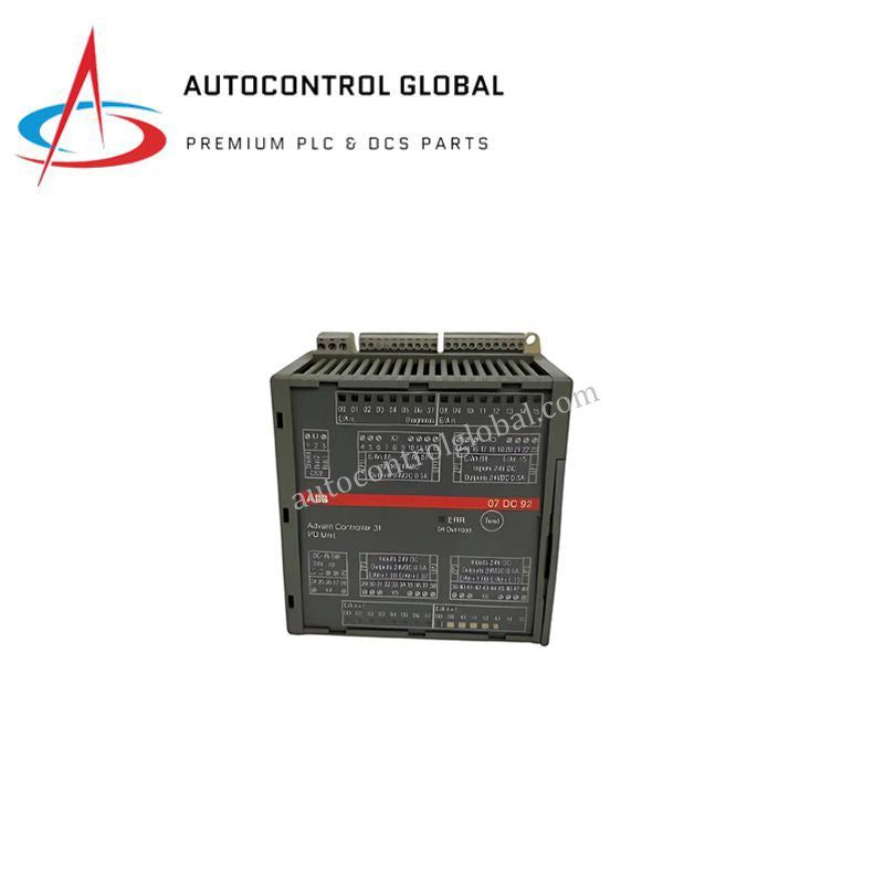
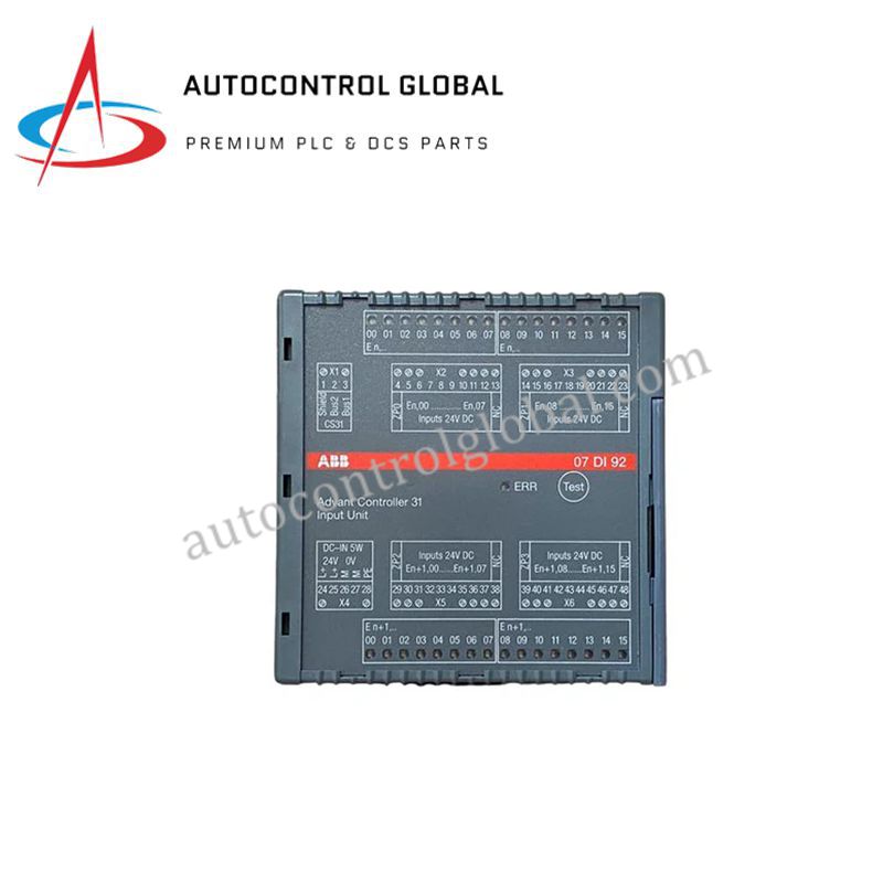


07KT94-98 GJR5252690R0001 ABB Advant Controller PLC Module
Manufacturer: ABB
-
Part Number: 07KT94-98 GJR5252690R0001
Condition:New with Original Package
Product Type: Multi I/O Modules
-
Country of Origin: Sweden
Payment:T/T, Western Union
Shipping port: Xiamen
Warranty: 12 months
ABB 07KT94-98 GJR5252690R0001 Advant Controller Series PLC Module
Configured for high-speed signal processing and control logic execution in ABB Advant Controller networks, the ABB 07KT94-98 GJR5252690R0001 (07KT94-98 PLC Module) provides direct physical/electrical execution.
Hardware Specifications
| Parameter | Specification |
|---|---|
| Model | 07KT94-98 GJR5252690R0001 |
| Brand | ABB |
| Origin | Sweden |
| Weight | 3.03 kg |
| Dimensions | 25.4 x 10.2 x 15.2 cm |
| Operating Temp | -20 to +60 deg C |
| Power Consumption | Standard backplane power load |
| Processor Architecture | 16-bit |
| Analog Inputs | 8 channels (0-10 VDC) |
| Analog Resolution | 12-bit |
| Analog Accuracy | +/-0.2% Full Scale |
| Digital Inputs | 24 VDC |
| Digital Outputs | 24 VDC / 0.5 A |
| Protection Rating | IP65 |
Deterministic Network Backplane & I/O Density Scaling
The internal 16-bit processor coordinates high-speed execution across 8 analog input channels (0-10 VDC) at 12-bit resolution and discrete 24 VDC digital channels. Operating within the local rack assembly, the module maintains high backplane bus communication velocity to preserve timing determinism across distributed nodes. The unit processes mixed signal data while supporting firmware flash compatibility and I/O density scaling across Advant Controller backplanes. Robust IP65 protection preserves internal circuit integrity during severe electrical and environmental transients.
Frequently Asked Questions
Q: What are the primary backplane power and current load considerations for the digital outputs?
A: You must calculate the combined switching current drawn by field devices connected to the 24 VDC digital outputs (rated up to 0.5 A per channel) to ensure total load currents do not exceed the local rack power supply limits during full concurrent operation.
Q: How do you maintain 12-bit signal accuracy on the 0-10 VDC analog input channels in high-noise environments?
A: Always route analog input wiring using twisted-pair shielded conductors isolated from AC power conduits. Connect cable shields to a single grounding point on the enclosure chassis to prevent ground loops that disrupt the +/-0.2% full scale conversion accuracy.
Field Installation Guidelines
Follow these technical procedures during field deployment to maintain hardware integrity:
- Power Disconnection: De-energize all primary rack supply voltages and field-side 24 VDC loops before installing or extracting the module from the subrack.
- Cabinet & Mechanical Mounting: Secure the module inside an industrial enclosure rated IP54 or higher to supplement the unit's IP65 protection. Maintain at least 50 mm of vertical ventilation space around the housing to facilitate airflow across the -20 to +60 deg C operating range.
- Signal Cabling & Grounding: Separate low-voltage analog cables (0-10 VDC) from high-current 24 VDC digital output wiring and AC distribution lines. Terminate all cable shields to the local earth ground bus using low-impedance grounding clamps.
- Wiring Inspections: Verify correct polarity across all 24 VDC power and I/O terminal connections prior to applying system power to prevent terminal damage or blown output stage fuses.