
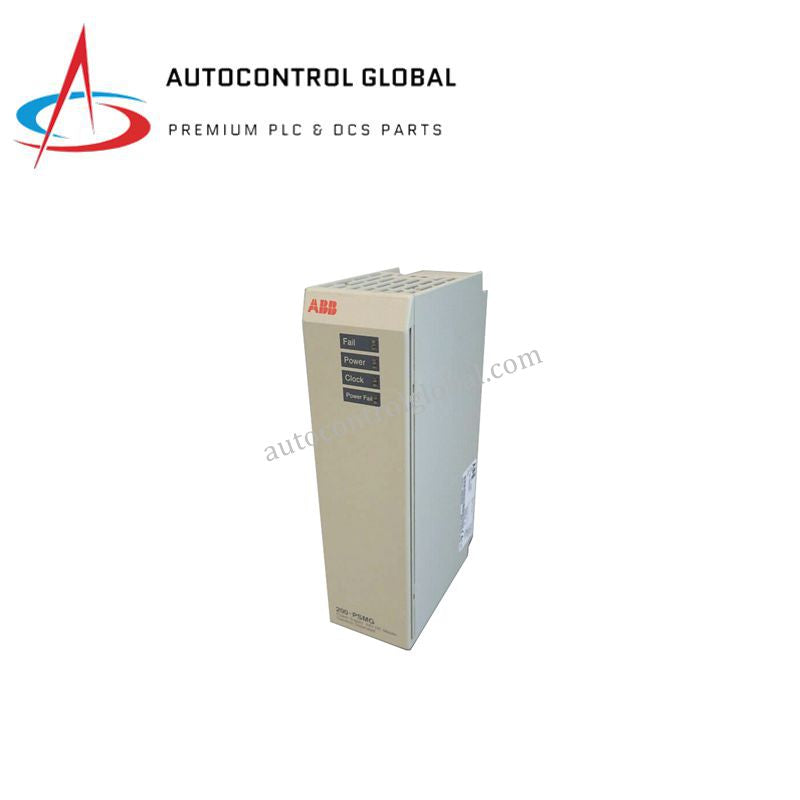
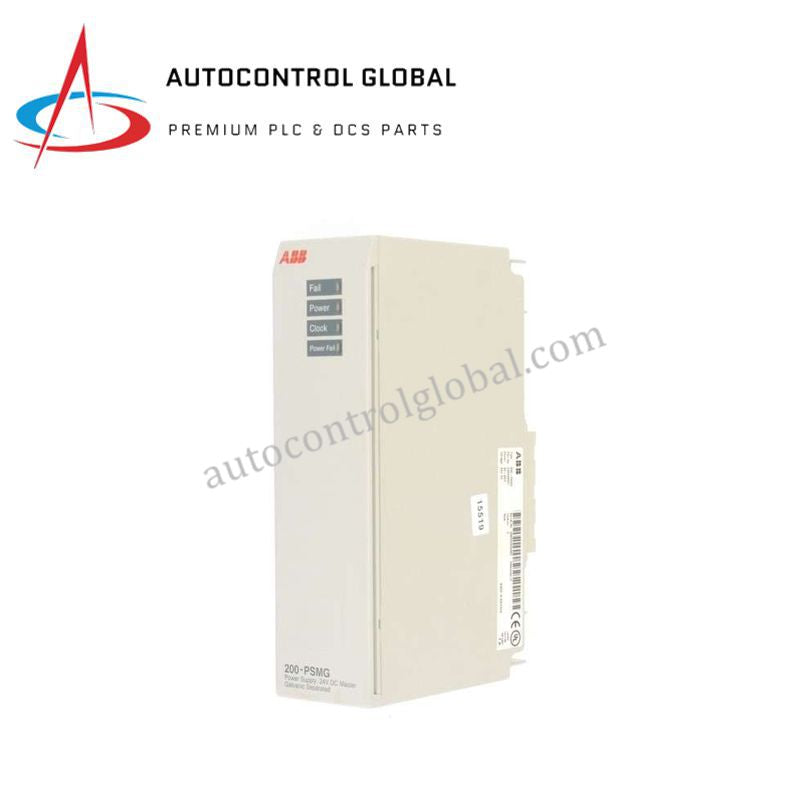


200-PSMG ABB Advant OCS Master Power Supply Unit
Manufacturer: ABB
-
Part Number: 200-PSMG
Condition:New with Original Package
Product Type: Power Supply Units
-
Country of Origin: Sweden
Payment:T/T, Western Union
Shipping port: Xiamen
Warranty: 12 months
ABB 200-PSMG Advant OCS Series 200 Master Power Supply Unit
Configured for direct backplane power regulation in ABB Advant OCS Series 200 control systems, the ABB 200-PSMG (200-PSMG Master Power Supply Unit) provides direct physical/electrical execution.
Hardware Specifications
| Parameter | Specification |
|---|---|
| Model | 200-PSMG (Product ID: EXC492898801) |
| Brand | ABB |
| Origin | Switzerland |
| Weight | 0.24 kg |
| Dimensions | 9.1 x 4.5 x 16.3 cm |
| Operating Temp | Standard industrial range |
| Power Consumption | 24 VDC nominal (19.2-30 VDC incl. max 5% ripple) |
| Input Fuse | 2 A slow 250 V IEC-127-3 micro fuse (TR5) |
| Inrush Current | Max 4 A for 10 ms |
| Hold Up Time | Max 0.3 ms power drop |
| Output Voltage | 7-9 VDC, max 2.2 A (1.8 A with PSSG modules) |
| Clock Frequency | 4, 6, 8, 12 MHz (auto-selected via CPU firmware) |
| Galvanic Isolation | 500 V AC rms between input and output |
| Connector Type | 200-BPP screw terminal block |
| Backplane Key Code | 7 |
Deterministic Network Backplane & System Power Execution
The module accepts a 24 VDC input and regulates output voltage to 7-9 VDC at up to 2.2 A across the 200-BPN backplane. Firmware flash compatibility within the CPU automatically selects clock frequencies of 4, 6, 8, or 12 MHz to stabilize backplane bus communication velocity. Built-in galvanic isolation of 500 V AC rms suppresses common-mode electrical noise across backplane channels. Visual diagnostic tracking relies on dedicated green LEDs for active power and clock status alongside red LEDs for fail and power fail states.
Frequently Asked Questions
Q: How does the power supply handle short voltage interruptions on the incoming 24 VDC line?
A: The module maintains output bus stability during incoming supply drops up to a maximum duration of 0.3 ms; line dips exceeding this threshold trigger internal power fail logic and illuminate the red Power Fail LED indicator.
Q: What current restrictions apply when using the unit alongside PSSG modules on the same backplane bus?
A: When operating in chassis configurations containing PSSG modules, you must limit the total maximum output current draw on the 7-9 VDC bus from 2.2 A down to 1.8 A to preserve thermal stability and voltage regulation.
Field Installation Guidelines
Follow these technical procedures during field deployment to maintain hardware integrity:
- Power Isolation: Turn off all primary 24 VDC field power sources before inserting or removing the power supply module from the backplane assembly.
- Backplane Alignment & Grounding: Verify that the backplane key code matches position 7 before mounting. Seat the module firmly onto the 200-BPN backplane to establish direct mechanical earthing connections.
- Wiring & Terminal Hookup: Connect incoming power leads securely to the 200-BPP screw terminal block. Ensure wire leads pass through isolated ducts away from high-voltage AC distribution wiring.
- Fusing & Overcurrent Verification: Inspect the 2 A slow-blow TR5 micro fuse prior to initial power application to confirm circuit continuity and correct rating alignment.