


51308112-100 Honeywell LCN Cable Datasheet & Technical Manual
Manufacturer: Honeywell
-
Part Number: 51308112-100
Condition:New with Original Package
Product Type: Coaxial Cable Assemblies
-
Country of Origin: USA
Payment:T/T, Western Union
Shipping port: Xiamen
Warranty: 12 months
Honeywell 51308112-100 Local Control Network Series
The Honeywell 51308112-100, also cataloged as the Honeywell 51308112-100 Coaxial Cable Set, operates as a dedicated hardware component for data transmission within Local Control Network (LCN) platforms.
Hardware Specifications
| Parameter | Specification |
|---|---|
| Model | 51308112-100 |
| Brand | Honeywell |
| Origin | USA |
| Weight | Manufacturer standard industrial rating |
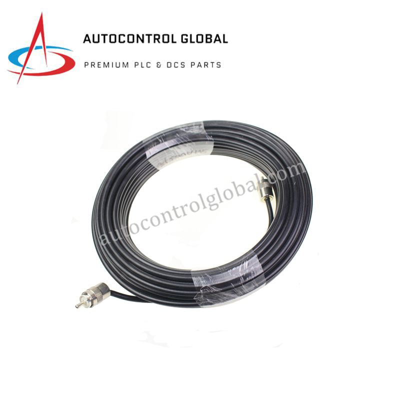
| Dimensions | 200 meters (Length) |
| Operating Temp | Manufacturer standard industrial rating |
| Power Consumption | Passive component (0 W) |
| Product Type | Coaxial Cable Set |
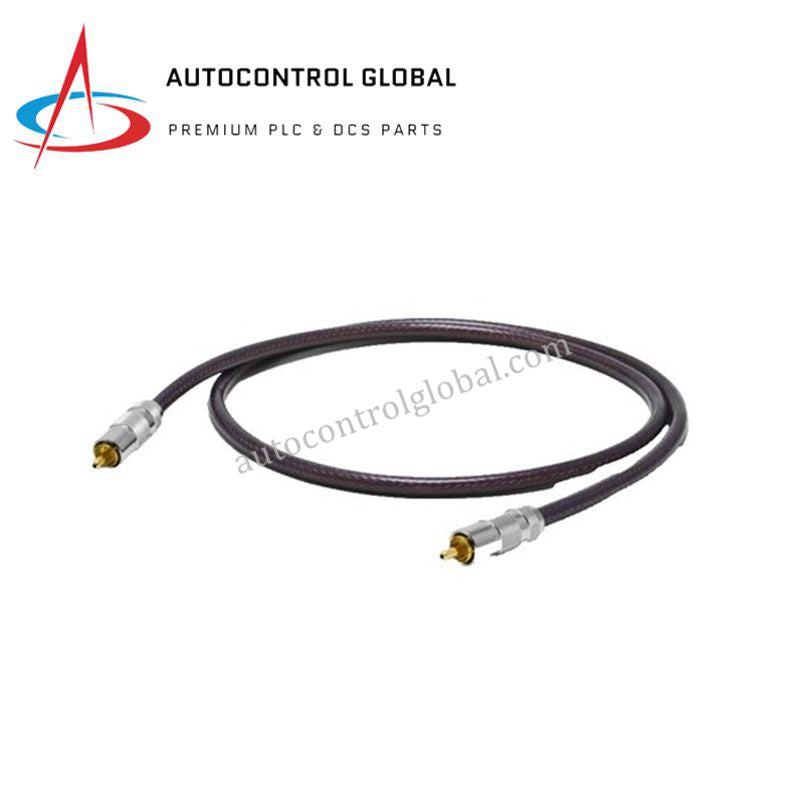
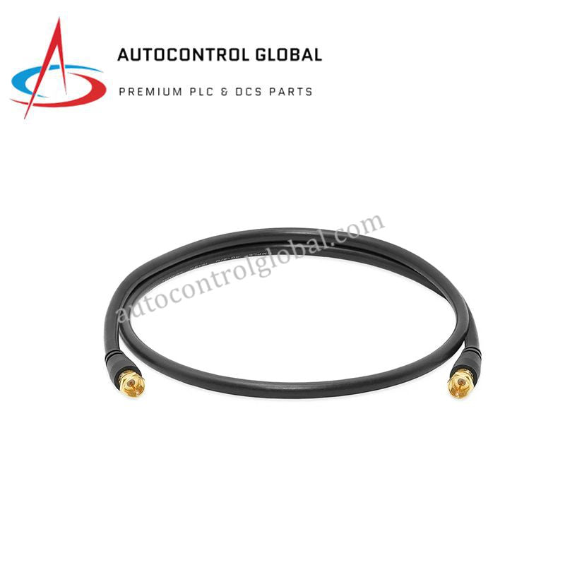
| Cable Type | RG11 coaxial with ferrite cores |
| Function | Data transmission in Honeywell LCN systems |
| EMI Protection | Integrated ferrites minimize signal interference |
| Compatibility | Replaces 51109181-100 model |
Process Control and DCS Instrumentation Channel Characteristics
The physical interface utilizes an RG11 coaxial construction framework optimized for high-frequency token-pass data communication across the Local Control Network (LCN). The cable assembly relies on a fixed 4-20 mA HART loop protocol physical isolation model via specific characteristic impedance matchings that control attenuation profiles over long distances. To enforce channel-to-channel isolation and mitigate transient high-frequency noise, the assembly features integrated inline ferrite cores. These passive magnetic components establish inductive choking barriers, providing robust electromagnetic interference (EMI) and cross-talk suppression while maintaining strict signal clarity for data transmissions across the DCS backbone.
Frequently Asked Questions
Q: Does this cable assembly support hot-swap insertion or connection changes while the LCN is actively communicating?
A: No, interrupting or disconnecting active LCN coaxial segments can disrupt token-ring network integrity and cause a localized or system-wide node communication failure. Any hardware changes or cable insertions must occur during planned maintenance windows or when network segments are properly bypassed.
Q: What are the backplane current consumption impacts of utilizing a 200-meter RG11 assembly?
A: As a completely passive coaxial assembly, the hardware does not draw power from the module backplanes. However, the transceiver cards interfacing with this 200-meter segment must operate within their prescribed line-driver milliamp tolerances to overcome baseline signal attenuation.
Field Installation Guidelines
- Bending Radius Constraints: Maintain the minimum physical bending radius prescribed for heavy-duty RG11 coaxial cables during layout. Kinking or over-bending the cable will deform the internal dielectric layer, altering local impedance metrics and generating data packet reflections.
- Ferrite Placement Verification: Ensure the integrated ferrite cores remain physically intact and correctly positioned at both cable termination ends. These units provide the primary line-to-ground common mode noise rejection prior to the signal entering the transceiver interface.
- Shielding Ground Grounding: Connect the external coaxial shields to the designated LCN system ground point in accordance with the standard plant engineering manual. Do not allow multi-point shield grounding paths that risk creating induced ground loops.