
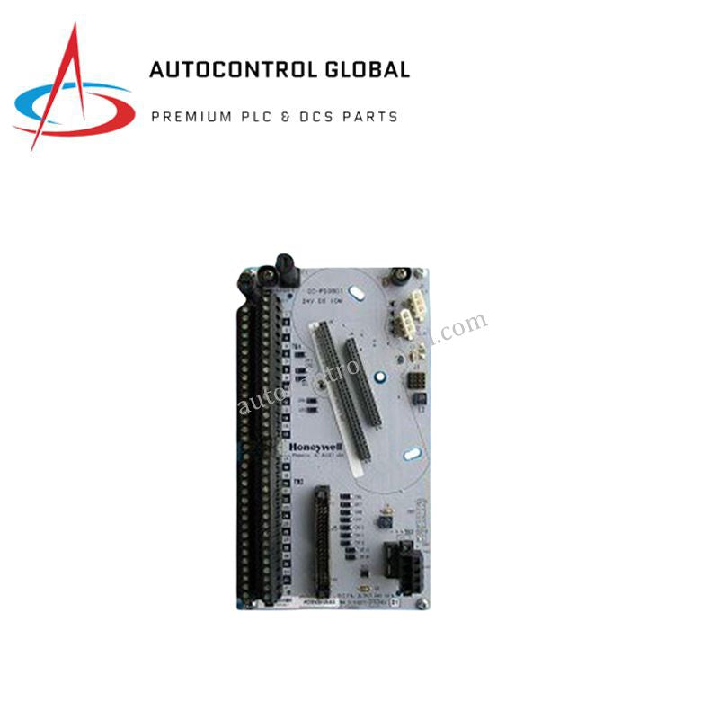


ABB 5N8D2392P001-B MPU-D PowerPC PLC Processing Modules
Manufacturer: ABB
-
Part Number: 5N8D2392P001-B/MPU-D
Condition:New with Original Package
Product Type: PLC Modules
-
Country of Origin: Sweden
Payment:T/T, Western Union
Shipping port: Xiamen
Warranty: 12 months
ABB 5N8D2392P001-B/MPU-D PLC Processing Module
The ABB 5N8D2392P001-B/MPU-D, also cataloged as the MPU-D PLC Processing Module, operates as a dedicated hardware component for high-speed algorithmic execution and multi-protocol data routing within ABB industrial control systems. Driven by a 32-bit PowerPC architecture paired with 2 GB RAM and 16 GB flash memory, this module executes real-time control programs across discrete and analog field channels.
Hardware Specifications
| Parameter | Specification |
|---|---|
| Model | MPU-D |
| Brand | ABB |
| Part Number | 5N8D2392P001-B |
| Origin | Standard Industrial Production |
| Weight | 0.5 kg |
| Dimensions | 96 x 96 x 76 mm |
| Operating Temp | -40 to +70 deg C |
| Power Consumption | 24 VDC nominal supply |
| CPU | 32-bit PowerPC |
| Memory | 2 GB RAM, 16 GB Flash Memory |
| Digital I/O Channels | 16 Digital Inputs, 16 Digital Outputs |
| Analog I/O Channels | 4 Analog Inputs, 2 Analog Outputs |
| Communication Protocols | Ethernet, Modbus, Profibus |
Deterministic Networks & Backplane Communication Velocity
Ensuring continuous real-time synchronization between local memory structures and distributed field I/O racks requires low-latency processing across the backplane bus interface. The MPU-D leverages high-capacity onboard memory to maintain predictable cycle times during concurrent Modbus, Profibus, and Ethernet frame execution. Integrated firmware flash compatibility enables seamless updates without disrupting backplane bus communication velocity or degrading clock synchronization across connected processor nodes.
Frequently Asked Questions
Q: How does the module indicate internal fault conditions during processing errors?
A: Integrated front-panel diagnostic status LEDs provide real-time visual alerts for system faults, module health, and active channel communication activity.
Q: What precautions should be observed regarding power supply input tolerances?
A: Connect a regulated 24 VDC external supply to the primary power terminals, ensuring line fluctuations do not exceed standard industrial limits to prevent unexpected processor resets.
Field Installation Guidelines
- Mount the module securely onto the mounting rack or DIN rail inside an IP54-rated cabinet to protect against airborne contaminants.
- Connect all Ethernet, Modbus, and Profibus communication cables using shielded twisted-pair media terminated with low-impedance connectors.
- Bond the shield braid directly to the cabinet functional earth grounding rail via a copper grounding jumper shorter than 30 cm.
- Maintain adequate physical spacing around top and bottom ventilation slots to allow passive thermal dissipation across the full -40 to +70 deg C operating temperature range.