
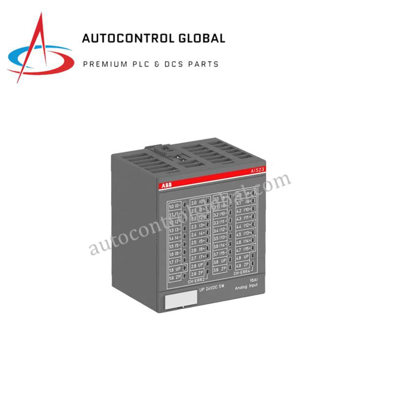
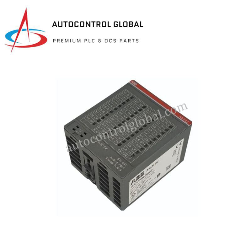
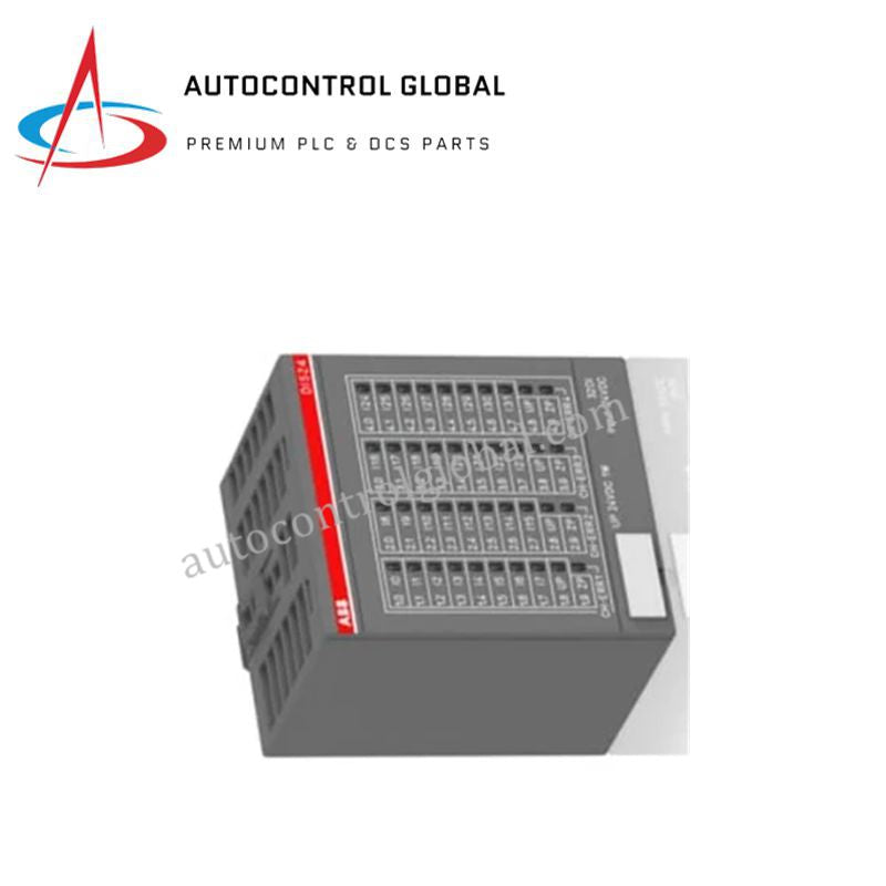


ABB AI723F-A2 ControlLogix PAC 8 Channel Analog Input Module
Manufacturer: ABB
-
Part Number: AI723F A2
Condition:New with Original Package
Product Type: Analog Input Modules
-
Country of Origin: Sweden
Payment:T/T, Western Union
Shipping port: Xiamen
Warranty: 12 months
ABB AI723F-A2 Analog Input Module
The ABB AI723F-A2, also cataloged as the AI723F-A2 Analog Input Module, operates as a dedicated hardware component for converting sensor voltage and current signals into precise digital values within ControlLogix PAC networks. The module processes analog field inputs across 8 isolated channels, digitizing raw electrical waveforms to provide continuous variable tracking for supervisory controllers and process hardware.
Hardware Specifications
| Parameter | Specification |
|---|---|
| Model | AI723F-A2 |
| Brand | ABB |
| Origin | USA |
| Weight | 1 kg |
| Dimensions | 120 mm x 80 mm x 60 mm |
| Operating Temp | Standard Industrial Range (0 to 60 deg C) |
| Power Consumption | Power derived from rack backplane bus |
| Number of Channels | 8 analog input channels |
| Supported Signal Types | Voltage and current signals |
| Host Integration | ControlLogix PAC interfaces |
| Mounting Type | Rack or panel mount compatible |
Backplane Bus Communication Velocity and Deterministic Networks
The AI723F-A2 analog input module attaches directly into the local rack frame, maintaining high backplane bus communication velocity across real-time execution cycles. Internal analog-to-digital convertors process field current and voltage loops continuously, updating control registers without introducing scan time jitter. Advanced board logic preserves firmware flash compatibility, preventing buffer overflow during maximum I/O density scaling across deterministic automation structures.
Frequently Asked Questions
Q: How does the AI723F-A2 module draw power for its internal analog-to-digital conversion circuits?
A: The card draws low-voltage logic power directly from the backplane rack assembly, requiring external field loops to be powered according to individual sensor wiring configurations.
Q: What precautions apply when inserting or removing the AI723F-A2 module from a live chassis?
A: Engineers must follow strict hot-swap safety protocols, ensuring field terminal blocks are unattached or isolated prior to module extraction to prevent backplane bus transients.
Q: How are voltage and current modes configured across the 8 analog channels?
A: Channel modes are selected during software system setup and hardware terminal block jumpers, matching the specific analog transducer electrical outputs.
Field Installation Guidelines
First, turn off power to the mounting rack and disconnect all 8 analog field loop terminals before positioning the AI723F-A2 module into the slot. Next, line up the circuit card edges with the enclosure guide channels, sliding the board back until the rear backplane connector locks into the bus receptacle. Then, secure the top and bottom retaining screws to establish chassis frame grounding and mechanical rigidity. Finally, run shielded twisted-pair cables for all analog voltage and current inputs, connecting signal cable shields to a single point ground bar to eliminate noise interference.