

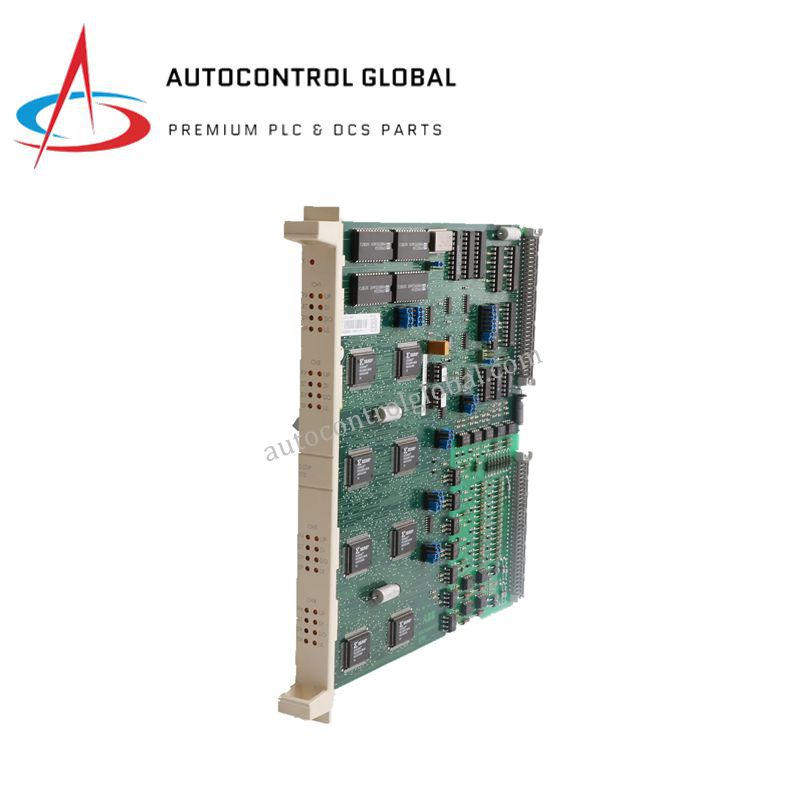
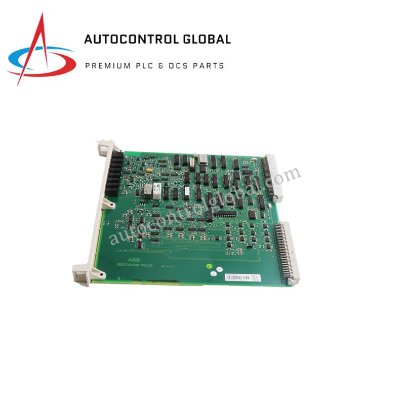


ABB DSPAD/02/647 Transformer Differential Relays
Manufacturer: ABB
-
Part Number: DSPAD/02/647
Condition:New with Original Package
Product Type: Protection Relays
-
Country of Origin: Sweden
Payment:T/T, Western Union
Shipping port: Xiamen
Warranty: 12 months
ABB DSPAD/02/647 Protection Relay Module
Configured for three-phase differential, overcurrent, and earth-fault protection in power transformer and generator-transformer networks, the ABB DSPAD/02/647 (DSPAD/02/647 Stabilized Differential Relay) provides direct physical/electrical execution. It evaluates winding short-circuits, interturn faults, interwinding shorts, and pole short circuits across systems rated up to 35 kV operating voltage and nominal 5 A current inputs. An integrated restraint and stabilization circuit suppresses false trip outputs during through-load spikes and external fault transients. Modern communication drivers interface directly with IEC 61850 network backbones and Modbus RTU serial links for real-time protection telemetry exchange.
Hardware Specifications
| Parameter | Specification |
|---|---|
| Model | DSPAD/02/647 |
| Brand | ABB |
| Origin | Sweden |
| Weight | Standard Relay Weight Class |
| Dimensions | Standard Flush-Mount Relay Dimensions |
| Operating Temp | Standard Industrial Range (-25 to +55 deg C) |
| Power Consumption | Standard Auxiliary Power Draw |
| Protection Functions | Three-phase differential, overcurrent, earth-fault |
| Fault Detection Types | Winding short-circuits, interturn faults, earth faults, interwinding faults, pole short circuits |
| Operating Voltage | Up to 35 kV |
| Current Input Rating | Up to 5 A |
| Stabilization Method | Percentage differential restraint against through-fault conditions |
| Protocols | IEC 61850, Modbus RTU |
| Application | Power transformers, generator-transformers |
Deterministic Substation Bus Networks and Firmware Compatibility
The module integrates high-speed bus algorithms to transmit real-time trip signals over IEC 61850 station bus architecture with minimal message latency. By locking internal sampling clocks directly to the substation network reference, the processing engine evaluates current vector shifts across differential channels without phase jitter. Solid-state output relays ensure rapid trip contact closure upon internal fault identification, while internal non-volatile flash memory maintains firmware flash compatibility, event logging records, and protection parameter files across power cycles.
Frequently Asked Questions
Q: How does the internal percentage restraint mechanism prevent false tripping during external fault conditions?
A: The restraint circuit measures the scalar sum of secondary currents passing through the protected zone to dynamically elevate the trip threshold, ensuring stability during high-magnitude through-fault currents and transformer magnetizing inrush conditions.
Q: What grounding procedures are required for the secondary current transformer (CT) input circuits?
A: Route all 5 A CT secondary leads directly to the module terminals using short, dedicated wiring runs, and establish a single solid connection to the substation safety earth bar at the terminal block to prevent ground loop currents from distorting signal measurements.
Q: Which network interfaces carry the digital telemetry and tripping commands?
A: The relay streams sampled values and Goose event messages via its dedicated IEC 61850 Ethernet port while simultaneously supporting Modbus RTU serial communication for local supervisory control and data acquisition (SCADA) systems.
Field Installation Guidelines
Mount the protective relay chassis vertically into a panel cutout using the front-mounting clamps, ensuring positive metallic contact with the grounded cabinet structure. Before tightening panel hardware, clear surrounding clearance areas to ensure unobstructed ambient air convection across heat sinks and internal components.
Connect current transformer inputs strictly according to phase polarity markings, using heavy-duty terminal blocks rated for secondary CT wiring. Apply a single functional earth ground strap from the enclosure earth point directly to the main cabinet grounding bus. Verify that IEC 61850 communication lines utilize shielded twisted-pair or fiber-optic cables routed well clear of high-voltage switching buses to prevent electromagnetic interference.