
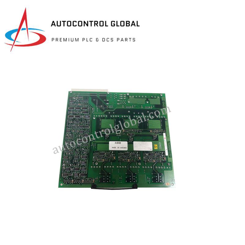
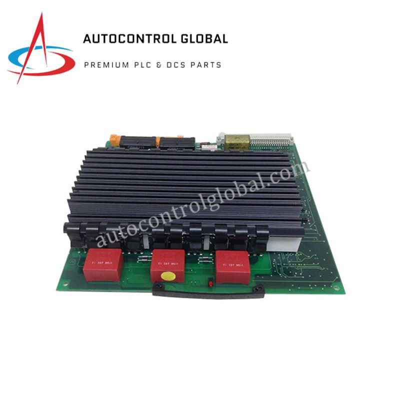
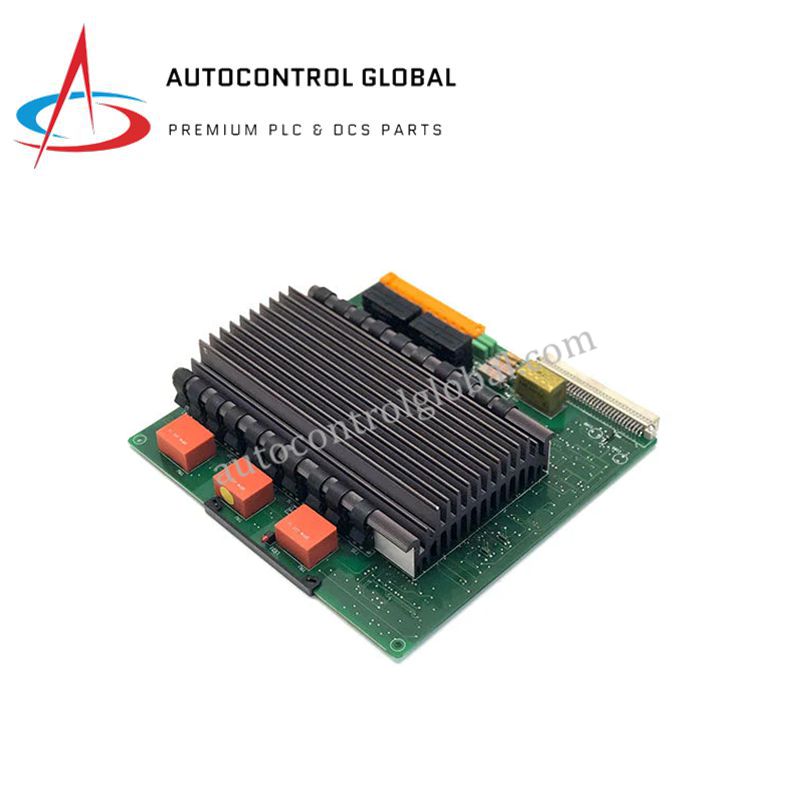


ABB DSQC-472 Protection Relay Control Module
Manufacturer: ABB
-
Part Number: DSQC472
Condition:New with Original Package
Product Type: Protection Relays
-
Country of Origin: Sweden
Payment:T/T, Western Union
Shipping port: Xiamen
Warranty: 12 months
ABB DSQC-472 Industrial Control Protection Module
The ABB DSQC-472, also cataloged as the DSQC-472 Microprocessor Protection Relay, operates as a dedicated hardware component for overcurrent, earth fault, and directional fault logic execution within industrial automation and power distribution platforms.
Hardware Specifications
| Parameter | Specification |
|---|---|
| Model | DSQC-472 |
| Brand | ABB |
| Origin | Sweden |
| Weight | 0.5 kg |
| Dimensions | 150 x 100 x 50 mm |
| Operating Temp | -20 to +60 deg C |
| Power Consumption | 24-48 VDC nominal input voltage |
| Protection Functions | Overcurrent, earth fault, directional fault protection |
| Communication Protocols | IEC 61850, DNP3 |
| Mounting Type | Panel-mounted or DIN-rail compatible |
Deterministic Network Backplane & System Integration
The module executes discrete relay logic algorithms through an integrated microprocessor engine while communicating across IEC 61850 and DNP3 industrial networks. Operating within a 24-48 VDC input range, the hardware manages high backplane bus communication velocity to ensure real-time telemetry updates and rapid fault actuation. The board architecture maintains deterministic response times across field networks without compromising firmware flash compatibility or scaling I/O density within complex control racks.
Frequently Asked Questions
Q: How does the unit process trip logic signals during network power disruptions?
A: The module relies on internally conditioned 24-48 VDC power input rails to maintain steady protection logic cycles; prolonged power drops trigger an internal fault state that opens designated alarm output contacts.
Q: What precautions are required when configuring IEC 61850 and DNP3 protocols on the same subrack node?
A: You must ensure proper subnet masking and unique node address assignments across all communication channels to prevent network packet collisions that could impair real-time fault telemetry transmission.
Field Installation Guidelines
Follow these technical procedures during field deployment to maintain hardware integrity:
- Power Disconnection: Isolate all incoming 24-48 VDC power sources and auxiliary sensing circuits prior to installing or removing the unit from the mounting assembly.
- Cabinet & Mechanical Mounting: Secure the housing onto standard DIN rails or panel cutouts inside an IP54 or higher rated control cabinet. Maintain at least 50 mm of vertical clearance around the module to facilitate natural thermal convection across the -20 to +60 deg C temperature range.
- Signal Cabling & Grounding: Route low-voltage communication leads and sensing inputs through shielded twisted-pair cables separate from high-voltage power lines. Connect cable shields directly to the main cabinet ground bar using low-impedance grounding clamps.
- Communication Port Isolation: Verify that all Ethernet and serial connections for IEC 61850 and DNP3 interfaces are strain-relieved and fully seated before applying system power to eliminate intermittent signal loss.