
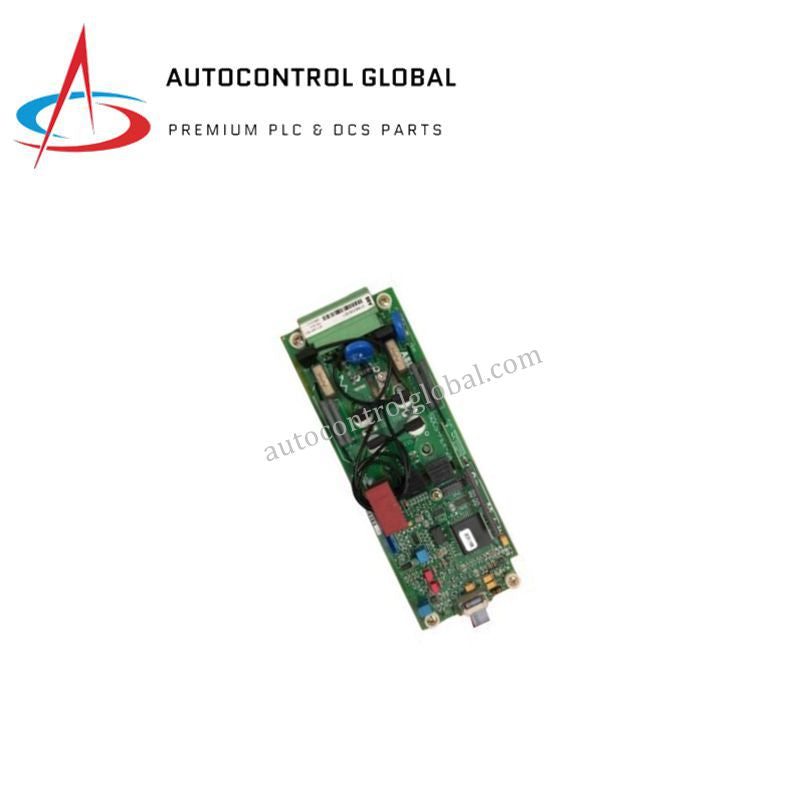
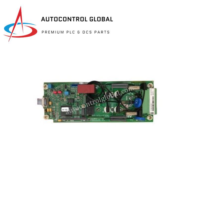
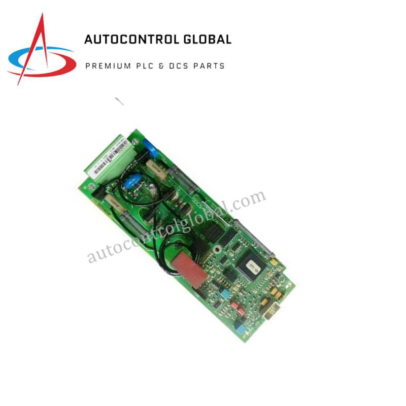


ABB SDCS-FEX-1 3ADT306000R1 DCS550 Field Excitation Board
Manufacturer: ABB
-
Part Number: 3ADT306000R1 SDCS-FEX-1
Condition:New with Original Package
Product Type: Field Excitation Boards
-
Country of Origin: Sweden
Payment:T/T, Western Union
Shipping port: Xiamen
Warranty: 12 months
ABB SDCS-FEX-1 DCS550 Field Excitation Board
The ABB SDCS-FEX-1 3ADT306000R1, also cataloged as the SDCS-FEX-1 Field Excitation Board, operates as a dedicated hardware component for field excitation current regulation within ABB DCS550 platforms.
Hardware Specifications
| Parameter | Specification |
|---|---|
| Model | SDCS-FEX-1 3ADT306000R1 |
| Brand | ABB |
| Origin | Switzerland |
| Weight | 0.1 kg |
| Dimensions | 8.3 x 4.4 x 13.3 cm |
| Operating Temp | Standard industrial range |
| Power Consumption | 24 VDC operating voltage |
| System Compatibility | ABB DCS550 Distributed Control System |
| Primary Function | Field excitation current regulation for synchronous machines |
Deterministic Network Backplane & System Integration
The module interfaces directly with the drive controller framework to compute excitation thresholds and drive field power stages. Operating at 24 VDC, the internal processing circuitry maintains stable control loops to prevent field current drift during dynamic load demands. High backplane bus communication velocity allows real-time telemetry exchanges with the central processing unit while preserving firmware flash compatibility across drive subracks. This tight hardware integration ensures predictable I/O density scaling when configuring parallel drive architectures.
Frequently Asked Questions
Q: What precautions prevent transient current spikes from damaging the 24 VDC control power logic?
A: You must install an external suppressed 24 VDC power supply with inline fast-acting fuses to isolate the excitation board from common-mode voltage spikes on the main control bus.
Q: How do firmware revisions impact swapping an SDCS-FEX-1 module inside a DCS550 drive frame?
A: You must verify that the replacement module matches the drive control unit firmware release to maintain full parameter mapping and avoid communication fault trips across the internal serial interface.
Field Installation Guidelines
Follow these technical procedures during field deployment to maintain hardware integrity:
- Power Isolation: De-energize all primary 3-phase power feeds and auxiliary 24 VDC supplies to the DCS550 drive cabinet before mounting or removing the module.
- Cabinet Mounting: Mount the board securely inside an enclosure rated IP54 or higher. Maintain at least 50 mm of vertical clear space around the housing to facilitate thermal convection.
- Cable Shielding & Routing: Route low-voltage excitation feedback wires in separate wire channels away from high-voltage AC power buses. Ground all shielded signal leads to the main cabinet earth bar using low-impedance grounding clamps.
- Connector Inspection: Verify that all multi-pin terminal ribbon connectors align correctly before applying power to avoid bent pins or intermittent backplane connections.