

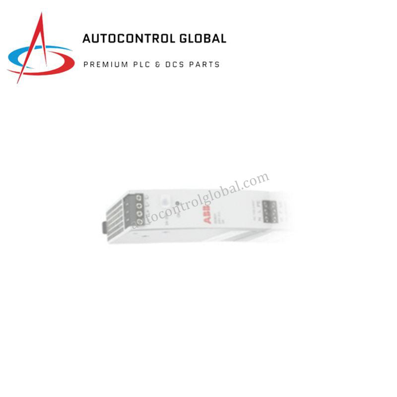
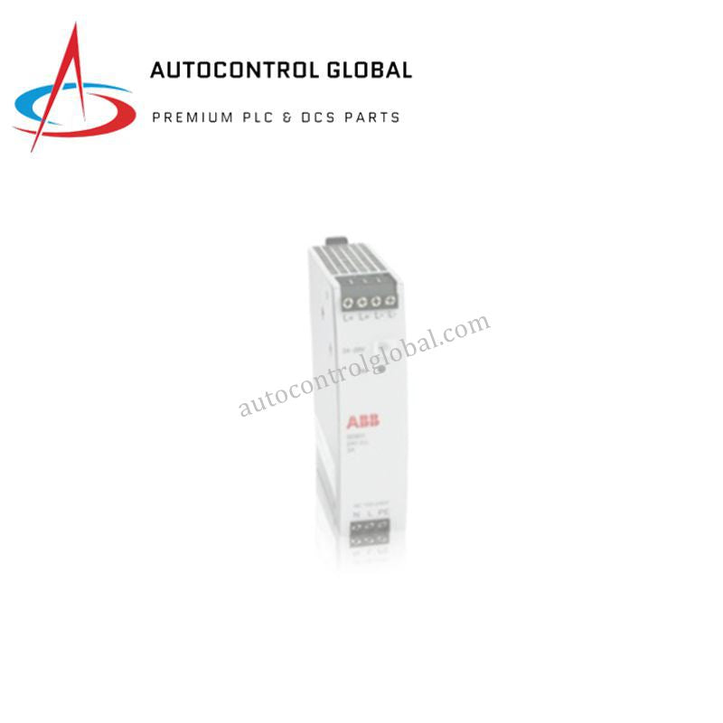


ABB SPS01-24V 2VAA008278R001 MPS IV Power Supply Module
Manufacturer: ABB
-
Part Number: SPS01-24V
Condition:New with Original Package
Product Type: Power Supply Modules
-
Country of Origin: Sweden
Payment:T/T, Western Union
Shipping port: Xiamen
Warranty: 12 months
ABB SPS01-24V 2VAA008278R001 Power Supply Module
The ABB SPS01-24V 2VAA008278R001, also cataloged as the SPS01-24V Power Supply Module, operates as a dedicated hardware component for direct regulated DC power distribution within ABB industrial automation platforms.
Hardware Specifications
| Parameter | Specification |
|---|---|
| Model | SPS01-24V (2VAA008278R001) |
| Brand | ABB |
| Origin | Sweden |
| Weight | 2 kg |
| Dimensions | Compact panel-mount form factor (<50 cm) |
| Operating Temp | Standard industrial operating range |
| Power Consumption | 24 VDC output at 10 A |
| ABB Type Designation | MPS IV |
| Mounting Type | Panel mounting |
| HS Code | 85044095 |
Deterministic Network Backplane & System Integration
The module supplies regulated 24 VDC auxiliary power across internal rack assemblies, maintaining steady voltage output to support system backplane bus communication velocity and logic processing modules. By isolating control electronics from input voltage spikes, the hardware protects adjacent I/O cards during high-density I/O density scaling operations while maintaining firmware flash compatibility across connected subrack sub-controllers.
Frequently Asked Questions
Q: What mounting clearance is required around the power module to ensure proper cooling? A: You should allow at least 50 mm of vertical clearance above and below the chassis to maintain unhindered thermal convection across internal heat sinks during continuous 10 A load execution.
Q: How do load transients affect the 24 VDC bus line when powering field actuators? A: The internal regulation circuit dampens voltage dips during high inrush currents, preserving steady bus power to prevent CPU resets or backplane communication dropping.
Field Installation Guidelines
Follow these technical procedures during field deployment to maintain hardware integrity:
- Power Disconnection: De-energize primary AC or DC mains supplies before mounting, wiring, or removing the power supply chassis from the control panel.
- Mechanical Mounting: Bolt the module firmly onto the enclosure panel using designated mounting slots to ensure chassis frame stability and solid protective earth grounding contact.
- Wiring & Shielding: Terminate 24 VDC output conductors using correctly sized gauge wire. Route low-voltage output lines away from high-voltage motor cables to minimize inductive noise coupling.
- Terminal Checks: Torque all power input and output terminal screws to manufacturer-specified limits prior to applying line power to prevent hot-spot resistance and terminal degradation.