
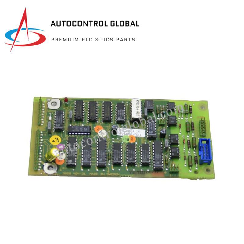
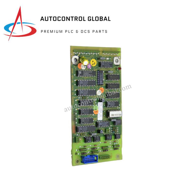


ABB YPH105E YT204001-FC VFD System Digital Speed Input Board
Manufacturer: ABB
-
Part Number: YT204001-FC YPH105E
Condition:New with Original Package
Product Type: Drive Boards
-
Country of Origin: Sweden
Payment:T/T, Western Union
Shipping port: Xiamen
Warranty: 12 months
ABB YPH105E Drive Board
The ABB YPH105E, also cataloged as the YPH105E Digital Speed Input Board (Ordering Code YT204001-FC), operates as a dedicated hardware component for pulse signal conditioning within ABB VFD platforms. The board conditions dynamic frequency pulse streams originating from tachometers or optical encoders, routing processed speed feedback directly into the drive closed-loop control subsystem.
Hardware Specifications
| Parameter | Specification |
|---|---|
| Model | YPH105E (Ordering Code: YT204001-FC) |
| Brand | ABB |
| Origin | Germany / Spain / USA |
| Weight | 0.8 kg |
| Dimensions | 16 cm x 16 cm x 12 cm |
| Operating Temp | Standard Industrial Range (0 to 55 deg C) |
| Power Consumption | Power derived from drive rack backplane bus |
| Signal Processing Type | Digital speed pulse input |
| Signal Conditioning | Onboard resistive network with status LEDs |
| Product Category | Drive Board / Input Module |
| Tariff Code | 85389091 |
Backplane Bus Communication Velocity and Deterministic Control
The YPH105E interface card connects into the drive control chassis backplane, maintaining high backplane bus communication velocity during real-time pulse conversion cycles. The onboard resistive attenuation circuit conditions high-frequency encoder pulse trains without inducing signal phase lag, enabling scalable I/O density integration within complex drive setups. Dedicated logic structures preserve firmware flash compatibility, maintaining deterministic pulse timing across drive control feedback loops.
Frequently Asked Questions
Q: How does the YPH105E board indicate channel operational status?
A: The board incorporates integrated LED status indicators that illuminate when pulse train signals are actively detected across the resistive network.
Q: How does the YPH105E interface with internal drive power distribution rails?
A: The module draws operational logic power directly through its backplane connector plug, eliminating external secondary power wiring.
Q: What precautions should be taken regarding encoder cable shielding when installing the YPH105E?
A: Shield braids from speed encoder signal lines must terminate at the nearest cabinet earth ground lug to isolate pulse channels from motor drive switching noise.
Field Installation Guidelines
First, turn off all main power sources to the variable frequency drive enclosure, allowing internal DC bus capacitors to discharge completely. Next, align the board edges with the chassis guide slots and insert the YPH105E module until the rear card edge connector fully seats into the backplane socket. Then, hand-tighten all board retention screws to maintain mechanical alignment and establish chassis grounding continuity. Finally, attach tachometer or encoder signal conductors to the terminal interface block, routing feedback cables separately from high-voltage AC motor power leads.