
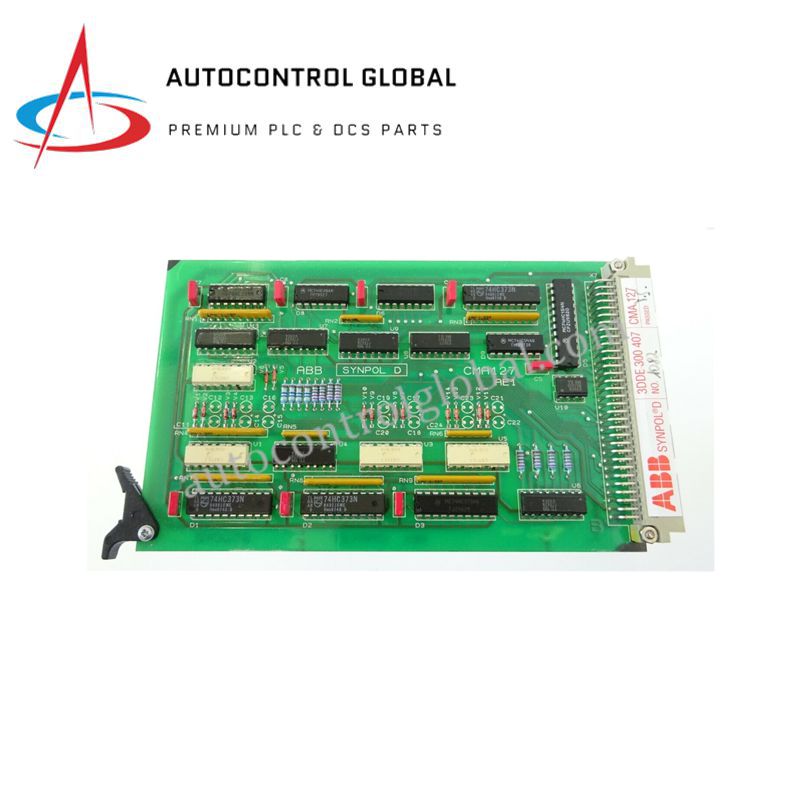
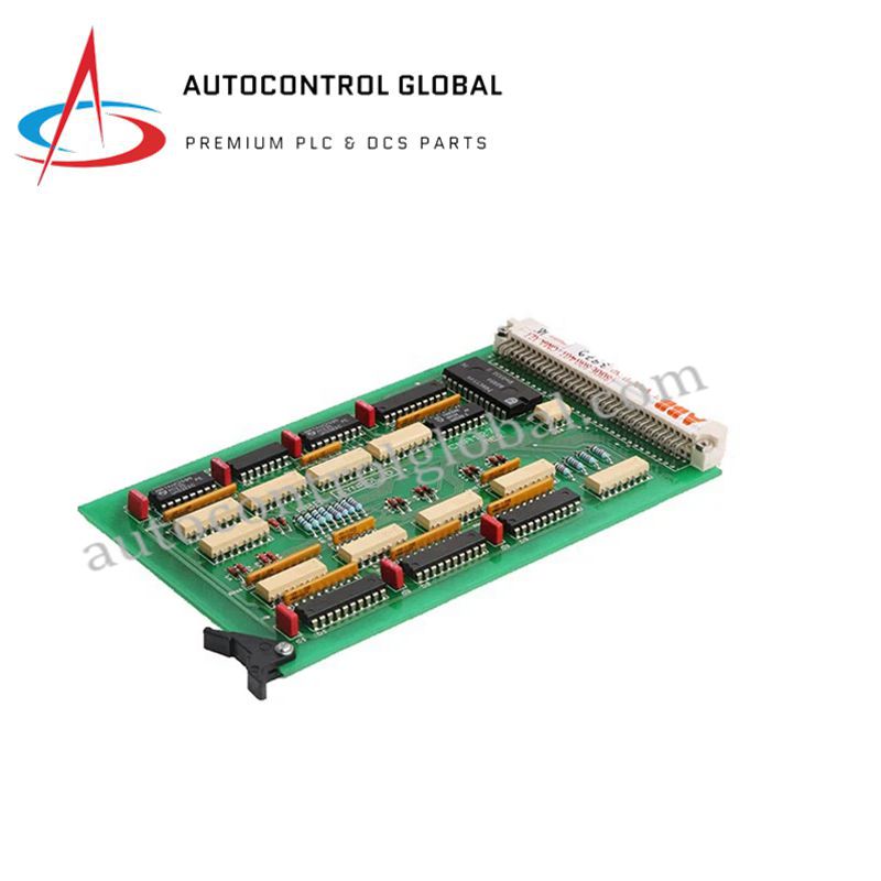


CMA127 3DDE300407 ABB Hydraulic Servo Control Module
Manufacturer: ABB
-
Part Number: 3DDE300407 CMA127
Condition:New with Original Package
Product Type: Servo Control Modules
-
Country of Origin: Sweden
Payment:T/T, Western Union
Shipping port: Xiamen
Warranty: 12 months
ABB CMA127 3DDE300407 Hydraulic Servo Control Module
The ABB CMA127 3DDE300407, also cataloged as the CMA127 Hydraulic Servo Control Module, operates as a dedicated hardware component for real-time control and monitoring of hydraulic systems within ABB industrial automation platforms.
Hardware Specifications
| Parameter | Specification |
|---|---|
| Model | CMA127 3DDE300407 |
| Brand | ABB |
| Origin | Switzerland |
| Weight | 0.2 kg |
| Dimensions | 120 x 80 x 30 mm |
| Operating Temp | -40 to +70 deg C |
| Power Consumption | 24 VDC operating voltage |
| Memory Capacity | 8 GB |
| Communication Interfaces | Ethernet, RS-485 |
| Primary Function | Hydraulic servo loop feedback and positioning execution |
Deterministic Network Backplane & System Integration
The module processes high-speed servo positioning loop algorithms while communicating across internal backplane buses and external networks via Ethernet and RS-485 interfaces. Utilizing 8 GB onboard memory for parameter storage and data logging, the hardware maintains backplane bus communication velocity during intensive real-time scan cycles. This optimized architecture prevents signal latencies, ensures firmware flash compatibility across subrack updates, and simplifies I/O density scaling across complex multi-axis control setups.
Frequently Asked Questions
Q: What precautions prevent signal jitter across the RS-485 serial communication loop?
A: Route all RS-485 control cables using twisted-shielded pair conductors, and install 120 ohm line termination resistors at both physical ends of the bus to maintain signal integrity.
Q: How do environmental temperatures between -40 and +70 deg C affect module installation in tight enclosures?
A: Maintain at least 50 mm of clear vertical spacing above and below the module chassis inside cabinet racks to prevent thermal dissipation issues during continuous high-load servo cycles.
Field Installation Guidelines
Follow these technical procedures during field deployment to maintain hardware integrity:
- Power Disconnection: De-energize all primary 24 VDC power feeds and hydraulic pump supply lines prior to inserting or extracting the module from the subrack chassis.
- Cabinet & Mechanical Mounting: Secure the module inside an IP54 or higher rated cabinet enclosure. Ensure the mounting rack provides adequate mechanical grounding contact against the chassis frame.
- Cable Shielding & Grounding: Separate low-voltage sensor feedback and communication lines from high-power field cabling. Connect all cable shields to the main cabinet grounding rail via low-impedance clamps.
- Interface Checks: Inspect Ethernet and RS-485 connector pins for alignment before applying system power to avoid bent pins and bus communication faults.