

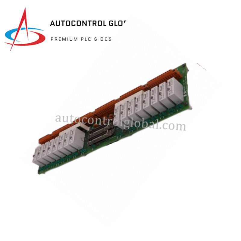
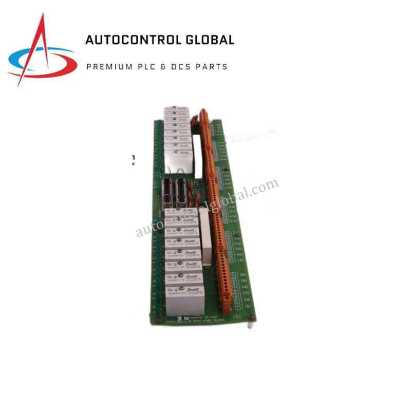


FC-TSHART-1620M Honeywell Safety Manager HART FTA
Manufacturer: Honeywell
-
Part Number: TSHART-1620M
Condition:New with Original Package
Product Type: Analog Input Field Termination Assemblies
-
Country of Origin: USA
Payment:T/T, Western Union
Shipping port: Xiamen
Warranty: 12 months
Honeywell FC-TSHART-1620M HART Analog Input Field Termination Assembly
Configured for HART-enabled analog measurement in Honeywell Safety Manager networks, the Honeywell FC-TSHART-1620M (TSHART-1620M HART Analog Input Field Termination Assembly) provides direct physical/electrical execution. This assembly connects field transmitters to SAI-1620M high-density analog input modules, routing 4-20 mA current loops while superimposing digital communication data. Precision input resistors condition incoming current signals into normalized voltage ranges for controller processing. Integrated fuse protection safeguards individual channels against overcurrent faults, and standard screw terminal blocks facilitate structured field wiring across process automation cabinets.
Hardware Specifications
| Parameter | Specification |
|---|---|
| Model | FC-TSHART-1620M |
| Brand | Honeywell |
| Origin | USA |
| Weight | 1.8 kg |
| Dimensions | 261 x 194 x 52 mm |
| Operating Temp | -20 to 60 deg C |
| Power Consumption | 3 mA quiescent current (excluding field loads) |
| Channel Count | 16 analog input channels (2 groups of 8) |
| Input Signal Range | 0-20 mA DC / 4-20 mA DC |
| Maximum Input Current | 25 mA DC |
| Input Resistance | 250 ohm (+/- 1%) |
| Signal Conversion Output | 0-4 VDC to SAI-1620M module |
| HART Communication | Supported |
| Channel Protection | 315 mA time-delay fuses |
| Mounting Type | Panel or DIN rail (TS32 / TS35 x 7.5 mm) |
4-20 mA HART Loop Protocol & Channel-to-Channel Isolation
Process control instrumentation relies on simultaneous analog control execution and digital parameter diagnostics without signal degradation. The FC-TSHART-1620M supports full 4-20 mA HART loop protocol integration, allowing two-way digital communication to overlay standard analog measurement channels. The module incorporates channel group isolation and precision internal resistance networks to block common-mode electrical interference. By maintaining strict electrical separation across input channels, the termination assembly prevents ground loops and transient voltage spikes from corrupting critical safety measurements or propagating faults back to the central controller.
Frequently Asked Questions
Q: How does the module handle HART digital signals combined with analog current inputs?
A: The internal 250 ohm precision resistors convert incoming 4-20 mA current loops into a stable 0-4 VDC range while preserving the superimposed HART frequency-shift keying (FSK) digital communication signals for the connected SAI-1620M module.
Q: What protection measures prevent field wiring faults from damaging the input card?
A: Each individual input channel features a dedicated 315 mA time-delay fuse that isolates overcurrent conditions instantly, protecting the internal termination circuitry and preventing loop failures from spreading across channel groups.
Q: How are field devices powered when connected to this termination assembly?
A: The assembly distributes external 30 VDC nominal power to field transmitters through dedicated terminal blocks while routing the return current loops safely through the internal conversion and protection networks.
Field Installation Guidelines
Mount the assembly securely onto a standard TS32 or TS35 x 7.5 mm DIN rail, or fasten it directly to the panel using designated mounting holes, ensuring adequate mechanical clearance around the module housing. Install end stoppers on both sides of the DIN rail to prevent lateral displacement under industrial vibration.
Route incoming field cables through dedicated wire ducts, maintaining physical separation between high-voltage power lines and low-voltage HART signal conductors. Strip conductor insulation to the recommended length, insert the wires into the screw terminal blocks, and tighten each screw securely to prevent intermittent contact.
Connect cable shield drain wires to the designated system earthing bar at a single grounding point to eliminate ground loops that interfere with analog measurement accuracy. Verify that all field loop voltages and HART communicator connections operate within specified thresholds before attaching the system interconnection cable to the controller module.