


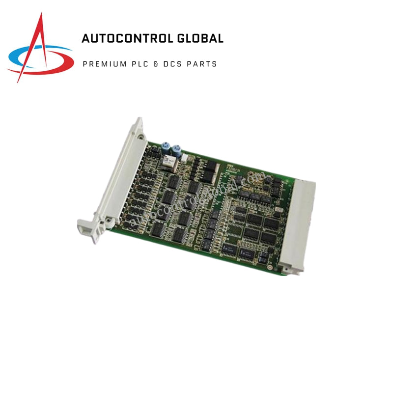


FC-TSRO-08UNI Honeywell Safety Manager Relay Assembly
Manufacturer: HONEYWELL
-
Part Number: FC-TSRO-08UNI
Condition:New with Original Package
Product Type: Safety Relay Output Field Termination Assemblies
-
Country of Origin: USA
Payment:T/T, Western Union
Shipping port: Xiamen
Warranty: 12 months
Honeywell FC-TSRO-08UNI Safety Relay Output Field Termination Assembly
The Honeywell FC-TSRO-08UNI, also cataloged as the TSRO-08UNI Safety Relay Output Field Termination Assembly, operates as a dedicated hardware component for relay-based signal switching within Honeywell Safety Manager platforms. Configured for high-integrity load control in industrial safety networks, this assembly routes controller output commands directly to external field actuators while maintaining strict galvanic isolation across channel boundaries. Each channel utilizes a triple-relay architecture to support SIL 3 safety compliance without requiring fault exclusions. Integrated fuse protection safeguards individual circuits against overcurrent events, while screw terminal arrays facilitate secure field wiring termination and power loop distribution across industrial control cabinets.
Hardware Specifications
| Parameter | Specification |
|---|---|
| Model | FC-TSRO-08UNI |
| Brand | Honeywell |
| Origin | USA |
| Weight | 0.3 kg |
| Dimensions | 274 x 109 x 71 mm |
| Operating Temp | -5 to 60 deg C |
| Power Consumption | 40 mA at 24 VDC |
| Channel Count | 8 relay-based safety output channels |
| Relay Configuration | Three relays per channel |
| Input Voltage Range | 24 VDC nominal (36 VDC maximum) |
| Maximum Output Voltage | 250 VAC / 250 VDC |
| Maximum Output Current | 2 A per fused output |
| Maximum Switched Load | 500 VA AC / 150 W DC |
| Fuse Rating | 2 A, slow-acting (5 x 20 mm) |
| Mounting Type | DIN rail (TS32 / TS35 x 7.5 mm) |
Channel-to-Channel Isolation & Safety State Execution
Safety instrumented systems demand robust electrical separation and fault containment to prevent loop failure propagation. The FC-TSRO-08UNI incorporates channel-to-channel isolation and redundant relay topologies to guarantee deterministic state execution during emergency shutdown sequences. By separating high-voltage field loads from low-voltage controller logic, the assembly prevents transient feedback from reaching the safety processor backplane. If an overcurrent fault occurs on an individual field loop, the corresponding 2 A slow-acting fuse clears instantly, isolating the faulted channel while maintaining continuous operation across the remaining safety outputs.
Frequently Asked Questions
Q: How does the triple-relay architecture achieve SIL 3 compliance on individual output channels?
A: Each of the eight channels integrates three discrete electromechanical relays arranged in a redundant configuration, satisfying fault-tolerance requirements for Safety Manager architectures up to SIL 3 without depending on external fault exclusions.
Q: What type of protection is provided for the normally open field contacts?
A: Every channel features a fused normally open field contact utilizing a 2 A slow-acting 5 x 20 mm fuse to protect against downstream short circuits and excessive current loads.
Q: How do technicians monitor the energized state of individual relay channels during operation?
A: Each output channel incorporates a dedicated LED indicator on the front module assembly to provide direct visual feedback of the energized relay state during runtime and troubleshooting.
Field Installation Guidelines
Mount the assembly securely onto a standard TS32 or TS35 x 7.5 mm DIN rail inside the control cabinet, ensuring adequate clearance for thermal dissipation around the 274 mm module housing. Install end stoppers on both ends of the mounting rail to prevent lateral displacement under industrial vibration.
Route external field cables through separate wire ducts, maintaining strict physical separation between high-voltage power lines and low-voltage control signals. Strip conductor insulation to the recommended length, insert the wires into the screw terminal blocks, and tighten each screw securely. Ensure that field load currents do not exceed the 2 A maximum threshold per channel.
Verify system grounding and check that control wiring matches the designated pinout before attaching the system interconnection cable from the Honeywell Safety Manager controller. Confirm that all channel fuses are properly seated and rated before applying primary power to the loop.