

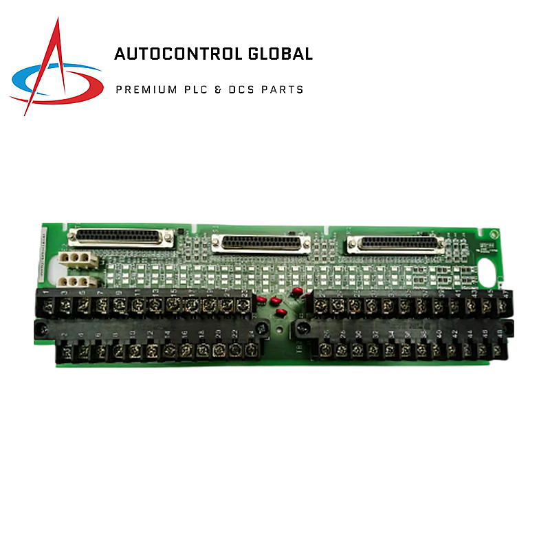
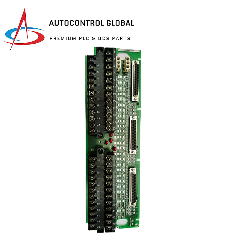


GE Fanuc | IS200TBAIH1CDD | Analog Input Terminal Board
Manufacturer: GE Fanuc
-
Part Number: IS200TBAIH1CDD
Condition:New with Original Package
Product Type: Analog Input Modules
-
Country of Origin: USA
Payment:T/T, Western Union
Shipping port: Xiamen
Warranty: 12 months
GE Fanuc IS200TBAIH1CDD Analog Input Terminal Board
The GE Fanuc IS200TBAIH1CDD, also cataloged as the IS200TBAIH1CDD Analog Input Terminal Board, operates as a dedicated hardware component for signal termination and analog signal processing within Mark VIe turbine control systems.
Hardware Specifications
| Parameter | Specification |
|---|---|
| Model | IS200TBAIH1CDD |
| Brand | GE Fanuc |
| Origin | USA |
| Weight | 0.85 kg |
| Dimensions | 10.16 cm x 33.02 cm |
| Operating Temp | -30 deg C to +65 deg C |
| Power Consumption | 24 VDC (nominal) |
| Analog Channels | 10 inputs, 2 outputs |
| Synchronization Accuracy | +/- 1 ns |
| Lead Resistance | 15 Ohm (max) |
Deterministic Network and I/O Density Scaling
The Mark VIe architecture utilizes the IS200TBAIH1CDD to maintain high-speed signal integrity across complex control loops. This board supports extensive firmware flash compatibility, allowing integration within simplex or triple modular redundant (TMR) control schemes. The board manages I/O density by providing 12 total channels, specifically engineered for high-frequency data acquisition where clock stability up to 200 MHz is required. Furthermore, the hardware facilitates Profinet or proprietary I/O bus communication, ensuring that analog loops maintain deterministic timing responses during critical turbine regulation events.
Frequently Asked Questions
Q: Does the IS200TBAIH1CDD support hot-swapping during active turbine operation?
A: While the terminal board itself acts as a passive termination point, the connected I/O packs should be configured according to Mark VIe hot-swap protocols. Always verify the status of the suicide relay before disconnecting cables to prevent unintended signal trips.
Q: How does the suicide relay function during a persistent fault state?
A: The onboard suicide relay monitors the output integrity. When the system detects a persistent internal fault or an out-of-range condition on the analog output, the relay transitions to an open state, effectively isolating the board from the field loop to prevent erroneous control commands.
Q: Can this board be used for mixed current and voltage signal inputs?
A: Yes. The board supports configurable jumpers for individual channels, allowing for mixed-mode operations including 1-5 VDC voltage inputs, as well as 0-20 mA or 0-200 mA output ranges for transducer control.
Field Installation Guidelines
- Mounting: Secure the terminal board to the DIN-rail or mounting plate using SMT-compatible hardware to ensure vibration resistance in turbine environments.
- Wiring: Terminate field wiring to the two 24-terminal blocks. Ensure wire gauges do not exceed #12 AWG to maintain proper terminal clamping force.
- Shielding: Attach cable shields directly to the designated shield terminal attachments on the block to suppress high-frequency electromagnetic interference.
- Jumper Configuration: Before applying 24 VDC power, verify that the physical jumper positions match the intended I/O type (voltage vs. current) for each specific channel.
- Validation: Use a calibrated multimeter to verify the 24 VDC excitation voltage at the terminal blocks before connecting sensitive transducer instrumentation.