
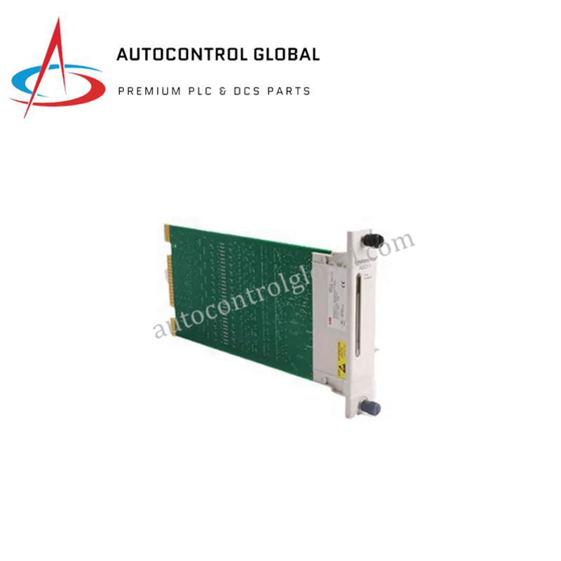
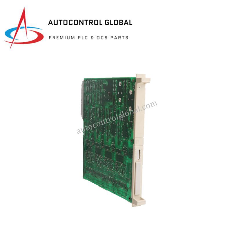
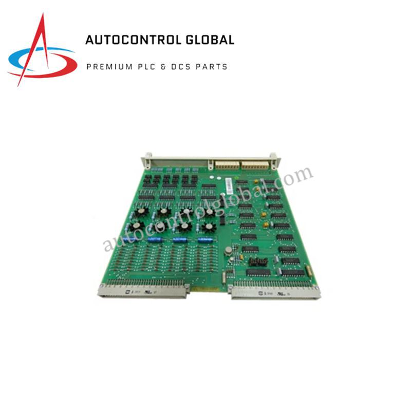


GJR5143700R1 ABB PLC DCS Processor Control Module
Manufacturer: ABB
-
Part Number: GJR5143700R1
Condition:New with Original Package
Product Type: Control Modules
-
Country of Origin: Sweden
Payment:T/T, Western Union
Shipping port: Xiamen
Warranty: 12 months
ABB GJR5143700R1 DCS/PLC Control Module
Configured for precise process control and real-time monitoring in ABB DCS/PLC systems, the ABB GJR5143700R1 (GJR5143700R1 Control Module) provides direct physical/electrical execution. The unit handles discrete logic execution across 16 digital inputs and 16 digital outputs while transmitting system status and operational commands through integrated Ethernet and RS485 communication interfaces.
Hardware Specifications
| Parameter | Specification |
|---|---|
| Model | GJR5143700R1 |
| Brand | ABB |
| Origin | Switzerland |
| Weight | 0.5 kg |
| Dimensions | 120 mm x 80 mm x 60 mm |
| Operating Temp | -40 deg C to +70 deg C |
| Power Consumption | 24 VDC nominal input |
| Memory Capacity | 256 KB |
| Digital Inputs | 16 channels |
| Digital Outputs | 16 channels |
| Communication Interfaces | Ethernet, RS485 |
| Mounting Type | Rack-mounted |
Backplane Bus Communication Velocity and Deterministic Networks
The GJR5143700R1 control module connects directly into the system rack backplane, maintaining high backplane bus communication velocity across real-time control loops. Internal firmware processing manages continuous scan cycles and memory addressing within the 256 KB onboard RAM, enabling high I/O density scaling across expanded automation nodes. Dedicated logic routines maintain firmware flash compatibility, preventing data loss and communication dropouts across deterministic networks.
Frequently Asked Questions
Q: How does the GJR5143700R1 interface with external 24 VDC power buses?
A: The module receives 24 VDC power directly from the backplane rail or field terminal contacts to power internal logic circuits and digital I/O channels.
Q: What operational guidelines apply to hot-swapping the GJR5143700R1 module during system operation?
A: System engineers must isolate connected 24 VDC field input and output wiring harness blocks prior to unseating the module from the rack backplane to prevent bus disruption.
Q: How are internal diagnostic faults signaled through the communication channels?
A: Integrated diagnostic routines process memory states and logic execution cycles, transmitting error registers via Ethernet and RS485 interfaces to the primary host system.
Field Installation Guidelines
First, turn off power to the rack chassis and verify that field I/O lines are de-energized before inserting the GJR5143700R1 card. Next, align the module circuit board with the chassis guide rails, sliding the assembly inward until the backplane connector fully seats into the motherboard socket. Then, tighten the panel retention screws to secure the module frame and establish chassis ground continuity. Finally, attach shielded Ethernet and RS485 communication cables, grounding all cable shields at a single panel ground bar to mitigate ambient electromagnetic noise.