


Honeywell 51404174-275 PMIO Power Supply Card
Manufacturer: Honeywell
-
Part Number: 51404174-275
Condition:New with Original Package
Product Type: Power Supply Modules
-
Country of Origin: USA
Payment:T/T, Western Union
Shipping port: Xiamen
Warranty: 12 months
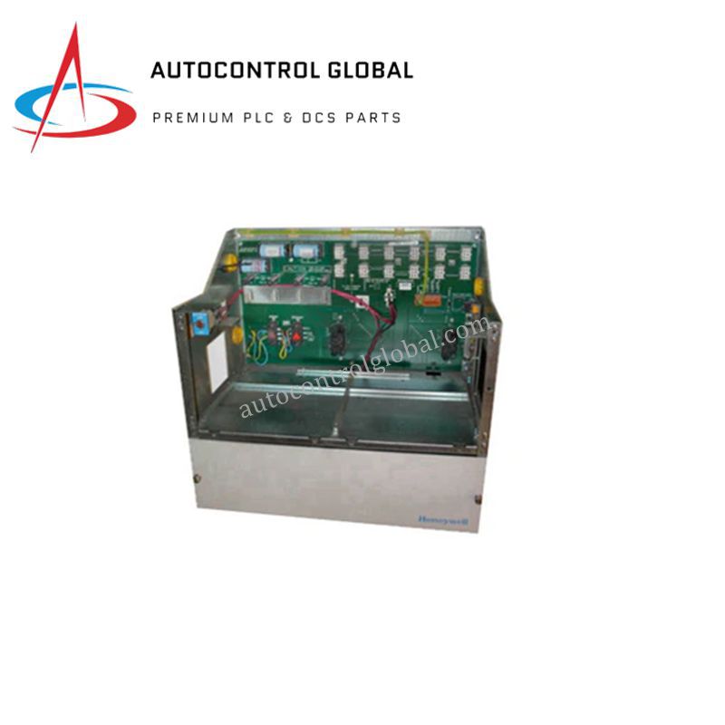
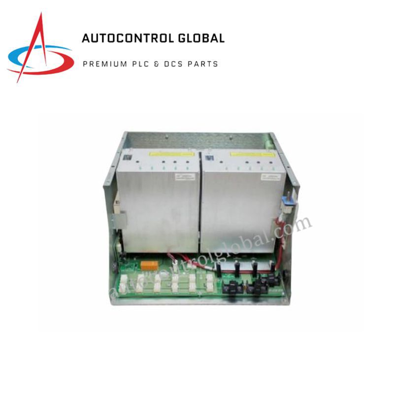
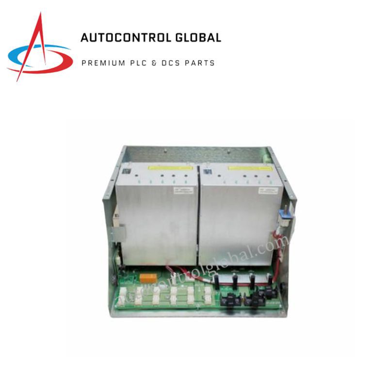
Honeywell MC-PSRX04 PMIO Series Redundant Power Supply Module
The Honeywell MC-PSRX04, also cataloged as the 51404174-275 Redundant Power Supply Module, operates as a dedicated hardware component for continuous 24 VDC power distribution within Honeywell PMIO family power supply systems platforms. The unit converts AC grid voltage directly into regulated DC power to drive discrete components and control bus channels in high-availability automation topologies.
Hardware Specifications
| Parameter | Specification |
|---|---|
| Model | MC-PSRX04 (Part Number: 51404174-275) |
| Brand | Honeywell |
| Origin | USA |
| Weight | 1.5 kg |
| Dimensions | 3.8 cm x 12.7 cm x 19.1 cm |
| Operating Temp | Industrial Grade Standard |
| Power Consumption | 85-264 VAC Input |
| Output Voltage | 24 VDC |
| Output Current | 16 A |
| Compatible Housing | 51404170-175 chassis |
| Certifications | CE, TUV, UL508, CSA |
Channel-to-Channel Isolation and Redundancy Integration
The module incorporates precise internal diode auctioning circuits to support parallel configurations without risk of back-feeding during component failure. Channel-to-channel isolation parameters ensure that a catastrophic fault on a single source input does not propagate to the common DC bus bar matrix. This architectural isolation boundary maintains continuous 24 VDC output capacity under dual-feed or asynchronous input switchover states.
Frequently Asked Questions
Q: How does the power supply handle internal component failures under full load conditions?
A: The hardware employs an active diode-ORing configuration. When installed inside a dual-module 51404170-175 chassis, a failure inside one unit triggers an instantaneous, bumpless transition of the 16 A current load to the secondary parallel module with zero microsecond drop on the 24 VDC line.
Q: What are the thermal dissipation mechanisms when outputting the full 16 A rating?
A: The module physical construction utilizes an aluminum faceplate housing acting as a passive heat sink. Heat dissipation relies on unrestricted vertical convection airflow paths inside the enclosure matrix to keep internal junction temperatures below thermal shutdown limits.
Field Installation Guidelines
- Chassis Engagement and Mechanical Locking: Slide the module completely into the assigned guide slots of the 51404170-175 housing. Tighten all integrated retaining screws to ensure proper electrical engagement of the heavy-duty rear connector pins with the chassis backplane.
- AC Input Conduit and Terminal Separation: Route the 85-264 VAC source cabling through separate wire paths distant from low-voltage DC logic and communication wires. Strip AC conductor insulation strictly to specifications to verify that no exposed wire strands project past the terminal pressure plates.
- Functional Grounding Verification: Ensure the chassis grounding terminal establishes a low-resistance path to the plant master instrument ground grid. All power distribution lines must utilize verified safety ground connections to protect against transient surge spikes and high common-mode noise induction.