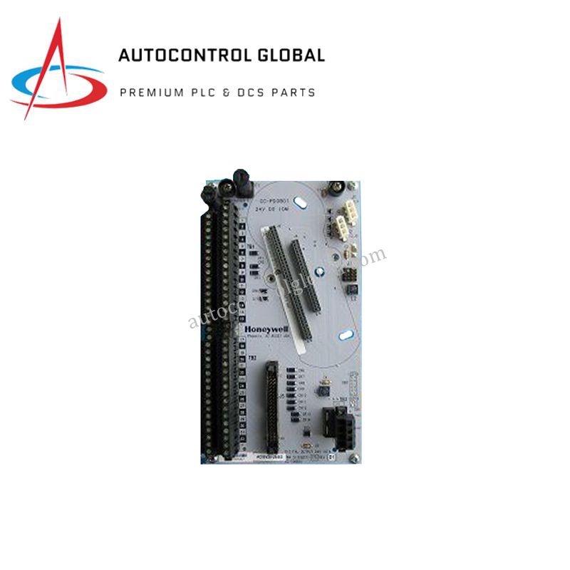
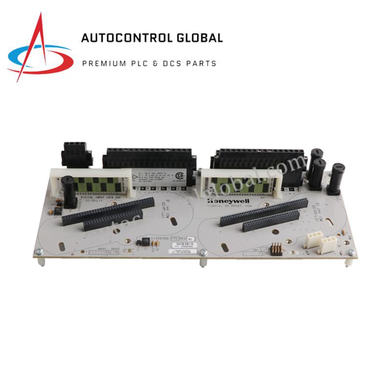
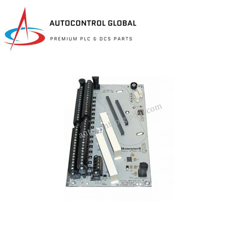


Honeywell DC-TDIL11 Series C Digital Input Module
Manufacturer: Honeywell
-
Part Number: DC-TDIL11
Condition:New with Original Package
Product Type: Digital Input Modules
-
Country of Origin: USA
Payment:T/T, Western Union
Shipping port: Xiamen
Warranty: 12 months
Honeywell DC-TDIL11 Series C Digital Input Module
Configured for high-speed signal acquisition in Honeywell Series C control systems, the Honeywell DC-TDIL11 (DC-TDIL11 Digital Input Module) provides direct physical/electrical execution. The hardware reads binary states from designated field apparatuses, converting incoming voltage levels into system-compatible logic bits across internal backplane registers.
Hardware Specifications
| Parameter | Specification |
|---|---|
| Model | DC-TDIL11 (Alternate Part Number: CC-TDIL11) |
| Brand | Honeywell |
| Origin | USA |
| Weight | 0.4 kg |
| Dimensions | 3.8 cm x 12.7 cm x 19.1 cm |
| Operating Temp | Industrial Grade Standard |
| Power Consumption | Current Consumption: 0.190 A |
| Input Voltage | 24 VDC |
| Number of Channels | 16 digital input channels |
| Response Time | < 1 millisecond |
| Isolation | 1500 V between channels and system |
| Certifications | CE, TUV, UL508, CSA |
Channel-to-Channel Isolation Parameters
The module incorporates precise galvanic separation components to isolate the internal processing logic from external field anomalies. With a rated 1500 V channel-to-system isolation boundary, the hardware suppresses common-mode voltage surges and ground loops. This architecture ensures that field-side electrical interference does not degrade data integrity within the concurrent 16-channel processing matrix.
Frequently Asked Questions
Q: How does the module handle backplane current loads during simultaneous 16-channel activation?
A: The module maintains a maximum continuous current consumption of 0.190 A from the backplane supply. The internal bus power tracking remains stable even when all 16 channels register concurrent high-state 24 VDC inputs under minimum latency conditions.
Q: What are the latency limits during redundant switchover execution within Series C systems?
A: The hardware supports redundant chassis configurations where a secondary pair takes over communication loops. Because the physical channel response time is less than 1 millisecond, the digital state table transfers across the redundant bus plane without losing track of input transition events.
Field Installation Guidelines
- Chassis Attachment and Pin Preservation: Insert the module vertically into the allocated Series C slot guide rails. Push the assembly backward firmly until the rear connector seats into the backplane, then lock the mechanical fasteners to maintain steady contact pressure.
- Shielding Ground Connection: Connect all instrument cable shields to a unified ground bar inside the marshaling cabinet. Keep all 24 VDC digital input signal lines separated from high-voltage AC electrical lines to eliminate inductive noise coupling on the signal wires.
- Terminal Wiring and Inspection: Strip the field wires to the prescribed length before locking them into the terminal block assembly. Perform routine pull tests to verify that no loose wire strands bridge adjacent channels, maintaining the physical integrity of the 1500 V isolation barrier.