
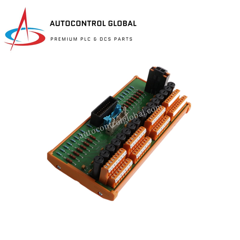
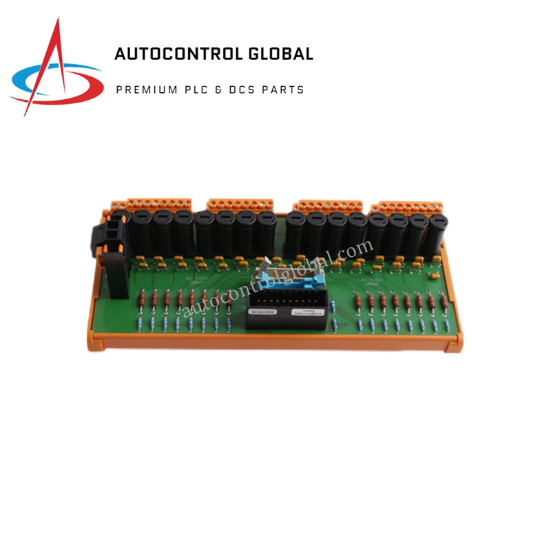


Honeywell FC-TSGAS-1624 Safety Manager Gas Detector FTA
Manufacturer: HONEYWELL
-
Part Number: FC-TSGAS-1624
Condition:New with Original Package
Product Type: Analog Input Field Termination Assemblies
-
Country of Origin: USA
Payment:T/T, Western Union
Shipping port: Xiamen
Warranty: 12 months
Honeywell FC-TSGAS-1624 Safe Gas and Flame Detector Input Field Termination Assembly
Configured for safe gas and flame detector signal processing in Honeywell Safety Manager networks, the Honeywell FC-TSGAS-1624 (FC-TSGAS-1624 Safe Gas and Flame Detector Input Field Termination Assembly) provides direct physical/electrical execution. This conformal-coated assembly routes 16 analog input channels from field-mounted sensors directly to high-density safety input modules while distributing regulated 24 VDC power. The unit conditions incoming current loops through precision 500 ohm resistance networks, transforming raw 0-20 mA or 4-20 mA field inputs into normalized 0-4 VDC voltage signals. Integrated slow-acting fuse networks safeguard individual channels against fault conditions. DIN rail mounting geometry enables rapid panel installation, and standard screw terminal blocks facilitate robust field wire termination.
Hardware Specifications
| Parameter | Specification |
|---|---|
| Model | FC-TSGAS-1624 |
| Brand | Honeywell |
| Origin | USA |
| Weight | 0.3 kg |
| Dimensions | 225 x 70 x 60 mm |
| Operating Temp | 0 to 60 deg C |
| Power Consumption | 3 mA (excluding field loads) |
| Channel Count | 16 analog input channels |
| Input Signal Range | 0-20 mA DC / 4-20 mA DC |
| Maximum Input Current | 25 mA |
| Input Resistance | 500 ohm (+/- 5%) |
| Signal Conversion Output | 0-4 VDC to SAI-1620M module |
| Output Accuracy | 0.1% |
| Channel Protection | 500 mA slow-acting fuse (5 x 20 mm) |
| Fuse Voltage Ratings | 250 VAC / 300 VDC |
| System Voltage | 24 VDC |
| Termination Type | Screw terminals (up to 2.5 mm2 / AWG 14) |
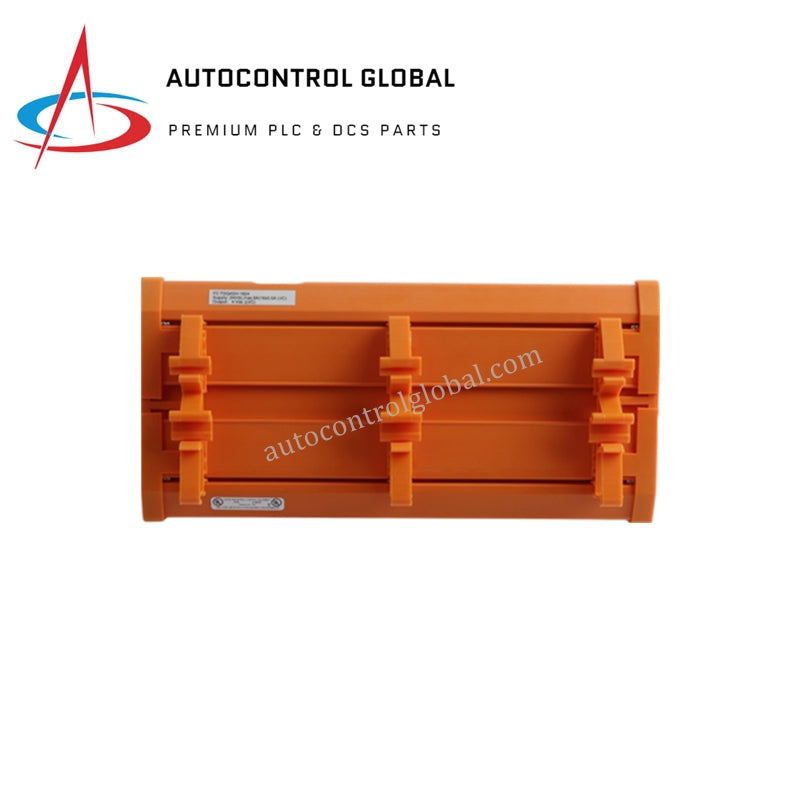
| Mounting Type | DIN rail (TS32 / TS35 x 7.5 mm, 226 mm length) |
4-20 mA HART Loop Protocol & Channel-to-Channel Isolation
Process control and safety instrumented systems demand rigorous electrical separation and deterministic signal conditioning to maintain loop integrity across complex automation networks. The FC-TSGAS-1624 incorporates channel-to-channel isolation and precision internal resistance networks to block common-mode electrical interference. By maintaining strict electrical separation across input channels, the termination assembly prevents ground loops and transient voltage spikes from corrupting critical safety measurements. The unit supports standard 4-20 mA current loops, ensuring reliable data exchange between field sensors and safety controllers without signal degradation.
Frequently Asked Questions
Q: How does the module handle overcurrent conditions on individual instrument loops?
A: Each field channel incorporates an independent 500 mA slow-acting fuse rated for 250 VAC / 300 VDC. An overcurrent event on a single instrument loop clears the specific channel fuse without disturbing power delivery or signal acquisition on adjacent channels.
Q: Can maintenance personnel replace individual channel fuses while the unit remains active?
A: Technicians can replace individual 5 x 20 mm fuses after isolating the specific channel field wiring. Field safety procedures dictate verifying loop current and voltage levels with an approved meter prior to fuse removal to prevent localized arc discharge.
Q: What impact does field cable resistance have on signal conversion accuracy?
A: The board converts incoming 0-20 mA current signals through internal 500 ohm precision resistors into a stable 0-4 VDC range with 0.1% accuracy, ensuring that standard field cable resistance does not degrade signal conversion prior to the termination network.
Field Installation Guidelines
Mount the assembly securely onto a standard TS32 or TS35 x 7.5 mm DIN rail, ensuring a minimum rail length of 226 mm for stable mechanical support. Fasten end anchors at both sides of the baseplate to prevent lateral movement along the DIN rail during vibration exposure.
Route incoming field cables through dedicated wire troughs, maintaining physical separation between high-voltage power lines and low-voltage signal conductors. Strip field wire insulation to 7 mm and insert conductors into the terminal blocks, tightening the screw terminals to a torque of 0.5 Nm. Ensure wire gauges do not exceed 2.5 mm2 (AWG 14).
Connect cable shield wires directly to the designated grounding terminals on the assembly. Land the shield drain wires at a single grounding point—typically at the field termination assembly grounding bar—to prevent ground loops from corrupting the analog signals. Verify that the system 0 V reference line connects solidly to the primary panel earth bus bar before energizing the 24 VDC external power supply.