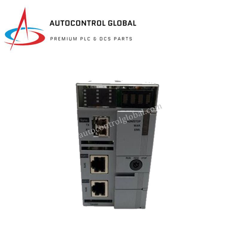
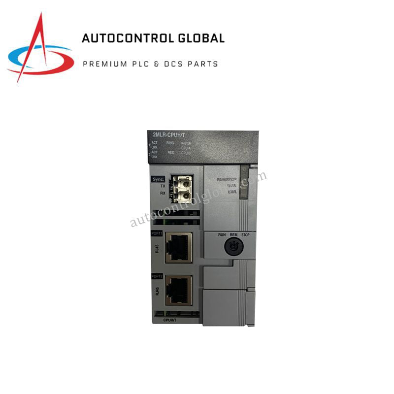
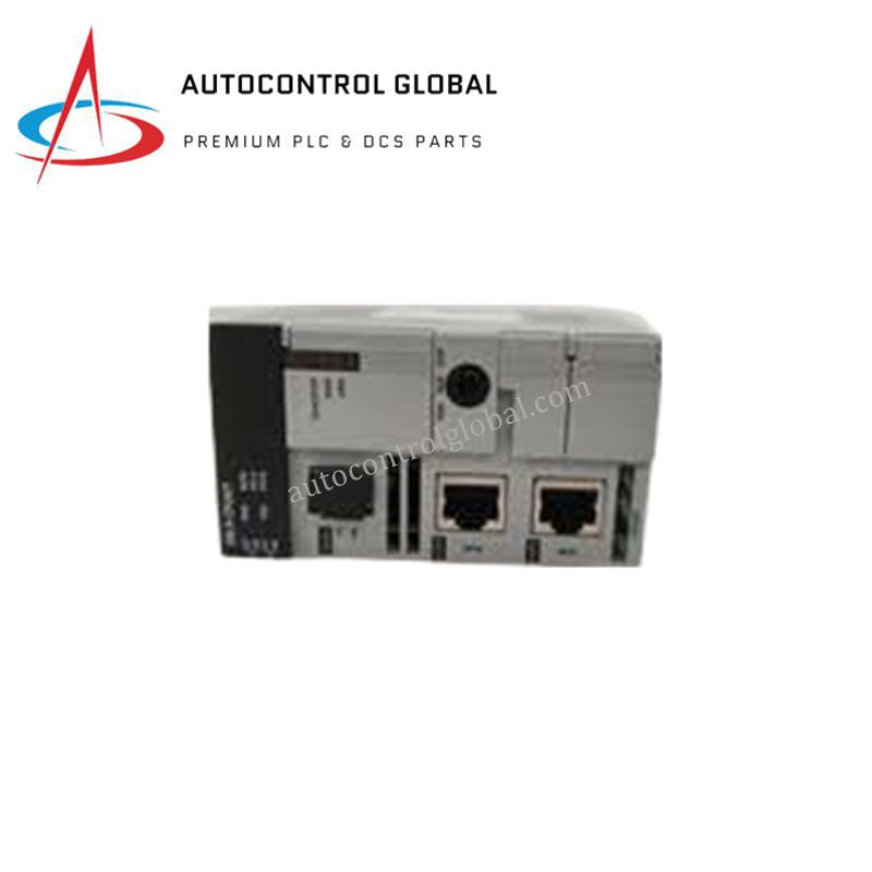


Honeywell MasterLogic-200R 2MLR-CPUH/T PLC Processor
Manufacturer: Honeywell
-
Part Number: 2MLR-CPUH/T
Condition:New with Original Package
Product Type: CPU Processors
-
Country of Origin: USA
Payment:T/T, Western Union
Shipping port: Xiamen
Warranty: 12 months
Honeywell 2MLR-CPUH/T MasterLogic-200R Programmable Logic Controller CPU
The Honeywell 2MLR-CPUH/T serves as the primary 2MLR-CPUH/T High-Speed Redundant CPU Module utilized to execute cyclic scanning, time-driven interrupts, and internal memory interrupts across MasterLogic-200R (ML200R) PLC platforms. The hardware processes structured automation logic using a scan-synchronous refresh and direct I/O control method to synchronize register variables over the local backplane.
Hardware Specifications
| Parameter | Specification |
|---|---|
| Model | 2MLR-CPUH/T |
| Brand | Honeywell |
| Origin | USA |
| Weight | 0.257 kg |
| Dimensions | 100 mm x 50 mm x 30 mm |
| Operating Temp | Industrial Grade Standard |
| Power Consumption | Current Consumption: 1,173 mA |
| Program Memory | 7 MB |
| Flash Memory | 16 MB |
| Max # of I/O Bases | 31 |
| Max # of Slots | 372 |
| Max Network/Remote I/O | 128,000 |
| Programming Languages | Ladder Diagram, SFC, Structured Text, Instruction List |
| Certifications | CE, TUV, UL508, CSA |
Channel-to-Channel Isolation and Redundancy Switching
The processor platform deploys a hardware-managed redundant switchover configuration operating across a dedicated dual-processor plane. The system relies on internal electrical boundaries to preserve channel-to-channel isolation limits, protecting core register data from external backplane noise and field transients. During a primary fault event, the memory synchronization matrix executes a bumpless transfer to the secondary standby CPU block, ensuring continuous logic evaluation without disrupting the 128,000 remote I/O variables.
Frequently Asked Questions
Q: How does the 2MLR-CPUH/T manage memory mapping when downloading new control logic?
A: The processor incorporates 7 MB of volatile program memory alongside a non-volatile 16 MB flash backup matrix. Changes undergo validation in the volatile sector before flashing, which prevents configuration mismatch faults across the redundant CPU pair during runtime operations.
Q: What are the backplane loading restrictions for a fully populated 372-slot architecture?
A: The module draws a continuous current of 1,173 mA from the local power rails. When designing systems that approach the maximum 31 expansion bases and 372 total slots, engineers must implement localized power supply cards to prevent voltage drop across the extended bus lines.
Field Installation Guidelines
- Chassis Pin Alignment and Mechanical Insertion: Seat the module firmly into the designated primary CPU slot of the MasterLogic-200R base unit. Push straight back until the rear connector fully interfaces with the backplane traces, then engage the mechanical locking tab to eliminate contact resistance.
- Shielding and Data Path Separation: Terminate all communication and remote I/O network cable shields at a dedicated master grounding bar inside the enclosure. Keep all low-voltage bus conduits separate from high-current AC motor leads or variable frequency drive cables to suppress electromagnetic noise.
- Grounding Integrity Inspection: Ensure that the PLC chassis base establishes a low-impedance copper link to the plant instrument ground network. Regularly inspect all terminal mounting screws to verify that physical vibration has not compromised the connection points or system isolation boundaries.