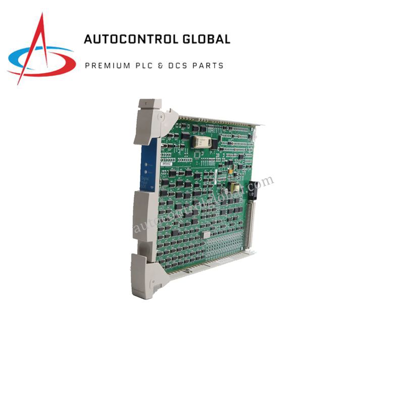


MC PDIS12 Honeywell 51402625-176 Sequence Card
Manufacturer: Honeywell
-
Part Number: 51402625-176
Condition:New with Original Package
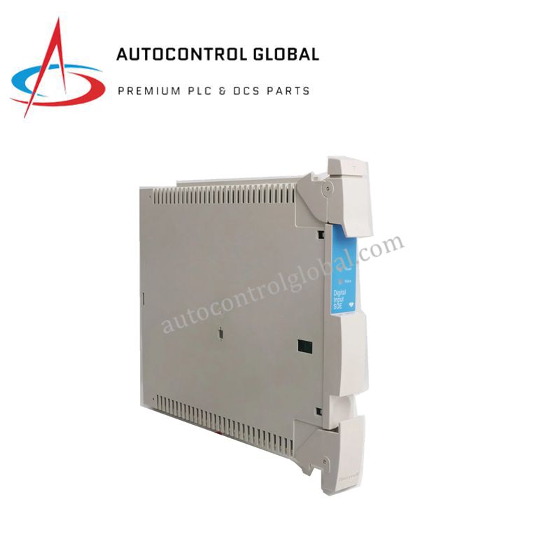
Product Type: Digital Input SOE Modules
-
Country of Origin: USA
Payment:T/T, Western Union
Shipping port: Xiamen
Warranty: 12 months
Honeywell 51402625-176 MC PDIS12 Sequence of Events Card
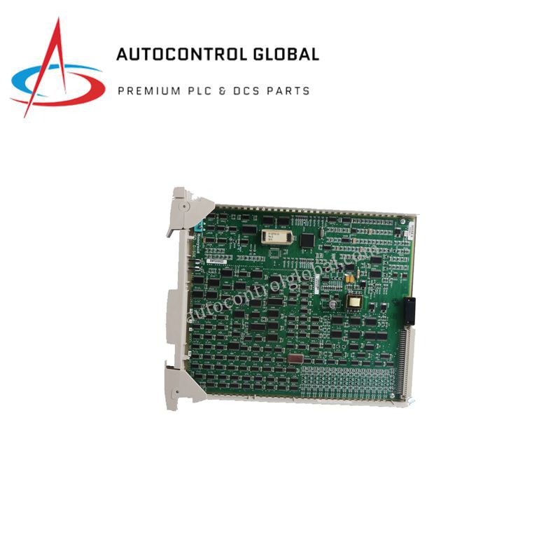
Configured for high-speed digital event recording in Honeywell Universal Control Network (UCN) systems, the Honeywell 51402625-176 (51402625-176 Digital Input SOE Module) provides direct physical/electrical execution. This module detects, transitions, and registers digital logic state changes with deterministic time-stamping to facilitate chronological fault analysis across process control nodes.
Hardware Specifications
| Parameter | Specification |
|---|---|
| Model | 51402625-176 |
| Brand | Honeywell |
| Origin | USA |
| Weight | 0.3 lbs (136 g) |
| Dimensions | 450 mm x 45 mm x 150 mm |
| Operating Temp | Industrial Grade Standard |
| Power Consumption | Energy-efficient design |
| Input Channels | 32 digital inputs |
| Input Voltage | 24 VDC |
| Functionality | Time-stamped logging of digital input transitions |
| Communication | Compatible with Honeywell UCN systems |
| Certifications | CE, TUV, UL508, CSA |
Process Control and Channel Isolation
The module executes real-time digital state capturing through discrete 24 VDC input circuits. To maintain data integrity across the high-speed backplane matrix, the system incorporates precise channel-to-channel isolation. This electrical isolation prevents transient voltage spikes, grounding differentials, and cross-channel electrical noise from corrupting the microsecond-level time-stamp accuracy required for sequence of events (SOE) diagnostics.
Frequently Asked Questions
Q: How does the module handle high-frequency input transitions without skipping sequence logs?
A: The hardware architecture utilizes dedicated per-channel transition filtering alongside an onboard buffer memory mechanism to capture and time-stamp rapid successive digital state changes prior to transmitting the structured data packets across the Honeywell UCN system interface.
Q: What are the installation requirements regarding input loop power configurations?
A: The digital input channels operate on a nominal 24 VDC loop threshold. External loop power supplies must be regulated to suppress ripple voltages, preventing false transition triggers and maintaining strict adherence to the module-specified timing resolution constraints.
Field Installation Guidelines
- Chassis Alignment and Insertion: Verify that the primary chassis power supply is isolated or that the local backplane segment meets hot-swap safety protocols prior to mechanical insertion. Align the module card edges evenly with the internal card cage guides to prevent pin deformation on the backplane connectors.
- Shielding and Grounding Protocol: Terminate all field wiring shield drains directly at the dedicated cabinet ground bar using low-impedance copper straps. Maintain definitive separation between low-voltage 24 VDC signal lines and high-voltage AC distribution conductors to prevent electromagnetic interference from inducing false transition logs.
- Terminal Block Engagement: Secure the field wiring harnesses to the front-facing terminal interfaces, ensuring a minimum structural thread engagement. Conduct routine torque verification to eliminate loose mechanical junctions that cause signal attenuation or intermittent contact behavior.