


MP-ZPSC16-100 Honeywell Processor Board | New & Original Stock
Manufacturer: Honeywell
-
Part Number: MP-ZPSC16-100
Condition:New with Original Package
Product Type: CPU Processors
-
Country of Origin: USA
Payment:T/T, Western Union
Shipping port: Xiamen
Warranty: 12 months
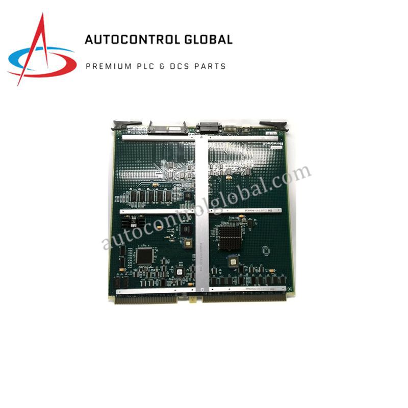
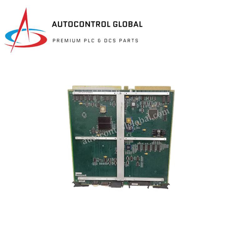
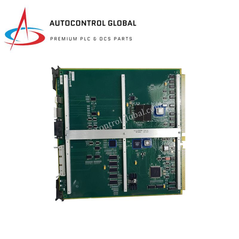
Honeywell MP-ZPSC16-100 Measurex Series
The Honeywell MP-ZPSC16-100, also cataloged as the Honeywell 51403519-160 Processor Board, operates as a dedicated hardware component for logic I/O management within Honeywell Measurex and legacy DCS platform networks.
Hardware Specifications
| Parameter | Specification |
|---|---|
| Model | MP-ZPSC16-100 (51403519-160) |
| Brand | Honeywell |
| Origin | USA |
| Weight | 0.84 kg (1.85 lbs) |
| Dimensions | 12.7 cm x 2.5 cm x 27.9 cm |
| Operating Temp | Manufacturer standard industrial rating |
| Power Consumption | Backplane logic load dependent |
| Function | Logic I/O management |
| System Compatibility | Honeywell Measurex and legacy DCS platforms |
| Upgrade Option | Compatible with K4SDR-16MW upgrade kit |
| Certifications | CE, TUV, UL508, CSA |
Process Control and DCS Instrumentation Architecture
The processor assembly relies on specialized circuitry to handle real-time logic execution across distributed control nodes. This architecture utilizes a dedicated 4-20 mA HART loop protocol interface for analog instrument communication, maintaining channel-to-channel isolation metrics to prevent signal corruption under high common-mode voltage differentials. Processing sequences are executed in sync with legacy backplane clock rates, and the hardware utilizes fixed cold junction compensation (CJC) curves when managing direct thermocouple terminations across the system bus.
Frequently Asked Questions
Q: What are the backplane current constraints when integrating the K4SDR-16MW upgrade kit with this board?
A: The board maintains strict power boundaries over the backplane bus. When installing the K4SDR-16MW upgrade kit, engineers must verify that total current consumption does not exceed the maximum milliamp rating allocated per slot by the host chassis power supply module.
Q: Can this processor board undergo live insertion or hot-swap procedures during operation?
A: No, this legacy hardware does not support live insertion. Complete system power-down is required prior to removing or inserting the processor board into the chassis to avoid physical component failure or backplane data bus corruption.
Field Installation Guidelines
- Chassis Alignment: Slide the processor board into the designated card guide slots of the chassis frame. Apply uniform pressure across the front faceplate until the backplane connectors seat completely and the locking mechanisms engagement is confirmed.
- Electrostatic Discharge (ESD) Prevention: Personnel must wear a grounded ESD wrist strap connected to the enclosure frame during installation to prevent static discharge from damaging the surface-mount logic ICs.
- Shielding and Conductor Separation: Ensure all digital communication cables and field loop wiring are physically separated from high-voltage AC lines inside the cabinet. Ground all shielded signal lines at a single reference point on the primary enclosure ground bar.