


PR6423/010-010+CON021 Emerson ePro Sensor Datasheet Technical Manual
Manufacturer: Emerson
-
Part Number: PR6423/010-010+CON021
Condition:New with Original Package
Product Type: Proximity Sensors
-
Country of Origin: Germany
Payment:T/T, Western Union
Shipping port: Xiamen
Warranty: 12 months
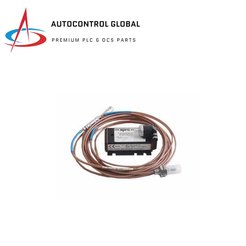
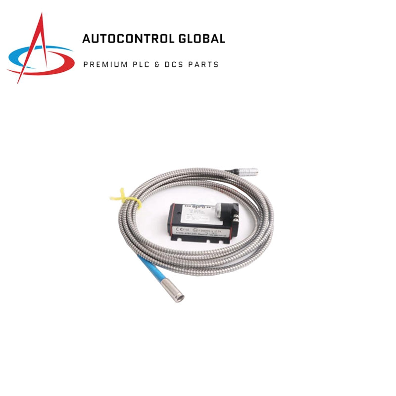
Emerson PR6423/010-010+CON021 ePro Series Eddy Current Sensor
The Emerson PR6423/010-010+CON021 serves as the primary PR6423 Eddy Current Sensor utilized to execute non-contact displacement and vibration monitoring across rotating machinery platforms. The hardware operates by generating a high-frequency electromagnetic field at the sensor tip, measuring the eddy-current loss induced within proximity of a conductive metallic shaft target. Operating in conjunction with the integrated CON021 signal converter module, the system translates relative structural micro-variations into linear electrical outputs, transmitting immediate shaft dynamics directly to supervisory vibration monitoring machinery.
Hardware Specifications
| Parameter | Specification |
|---|---|
| Model | PR6423/010-010+CON021 |
| Brand | Emerson (ePro Series) |
| Origin | Germany |
| Weight | 0.45 kg |
| Dimensions | 8 mm sensor tip diameter (standard structural enclosure) |
| Operating Temp | -40 to 125 deg C |
| Power Consumption | Driven by supply voltage; typically 12-24 VDC external input |
| Transducer Type | Non-contact eddy current displacement sensor |
| Signal Conditioning | CON021 external converter matching assembly |
| Analog Output | 0-10 VDC voltage or 4-20 mA current loop (selectable) |
| System Target | Ferromagnetic and non-ferromagnetic rotating shafts |
| Structural Rating | Sealed rugged casing for continuous submersion in oil environments |
Eddy-Current Probe Scaling and Rotor Dynamics
The calibration matrix of the PR6423/010-010+CON021 relies on precise eddy-current probe scaling to establish a linear voltage or current relation relative to the physical air gap. The target distance is measured through gap voltage validation, targeting standard reference baselines (such as -10 VDC targets in typical proximity configurations) to align the sensor within its optimal measurement track. This linear electrical output maps static positioning and high-frequency dynamic motion, enabling the analysis of complex rotor dynamics including oil whirl, shaft eccentricity, and synchronous unbalance. Cross-talk suppression loops are integrated into the oscillator circuitry of the CON021 converter, blocking adjacent high-frequency magnetic interferences from distorting the displacement data.
Frequently Asked Questions
Q: How is the gap voltage validation executed during static field calibration?
A: Adjust the mechanical mounting depth of the 8 mm probe housing relative to the stationary target shaft until the electrical output matches the specified nominal midpoint (e.g., -10 VDC on standard reference instruments). This ensures the sensor operates in the center of its linear voltage curve, preventing saturation during high-amplitude shaft vibrations.
Q: Can the sensor probe wire be cut or spliced to modify field routing length?
A: No. The integrated coaxial cable length forms an integral component of the internal tuned LC oscillator tank circuit. Cutting or altering the factory cable length changes the systematic inductance and capacitance, completely invalidating the pre-calibrated eddy-current probe scaling factor.
Q: What mechanisms prevent cross-talk suppression failures when multiple PR6423 probes are installed on the same bearing housing?
A: Cross-talk suppression is maintained by ensuring proper physical separation between probe tips (minimum of three times the tip diameter) and using the CON021 converter's internal frequency-separation filters, preventing overlapping electromagnetic driver fields from corrupting individual channel data.
Field Installation Guidelines
- Thread the 8 mm sensor body into the tapped bearing housing boundary, checking the mechanical clearance before locking the assembly with the integrated hex jam nuts.
- Secure the specialized coaxial cable using insulated cleats inside the machine casing, maintaining a minimum bend radius of 25 mm to prevent structural degradation of the internal shield layer.
- Route the analog signal lines from the CON021 converter through dedicated, grounded steel conduits, keeping the wiring separated from high-current three-phase motor lines by at least 300 mm.
- Ground the outer braid shield of the transmission wire exclusively at the monitor rack side to eliminate potential ground loop currents across the continuous -40 to 125 deg C operational path.