



Safety Manager Termination Assembly | Honeywell FS-TSRO-0824
Manufacturer: Honeywell
-
Part Number: FS-TSRO-0824
Condition:New with Original Package
Product Type: Digital Output Field Termination Assemblies
-
Country of Origin: USA
Payment:T/T, Western Union
Shipping port: Xiamen
Warranty: 12 months
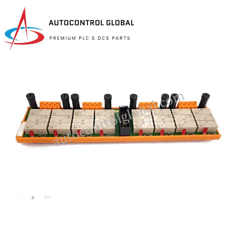
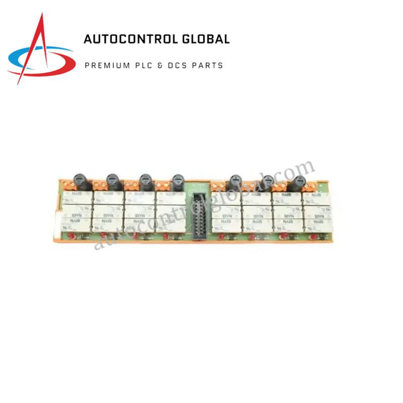
Honeywell FS-TSRO-0824 Digital Output Field Termination Assembly
The Honeywell FS-TSRO-0824, also cataloged as the FS-TSRO-0824 Digital Output Field Termination Assembly, operates as a dedicated hardware component for managing eight floating, non-commoned output channels within Safety Manager platforms.
Hardware Specifications
| Parameter | Specification |
|---|---|
| Model | FS-TSRO-0824 |
| Brand | Honeywell |
| Origin | USA |
| Weight | 0.5 kg to 2.0 kg |
| Dimensions | 300 mm x 70 mm x 62 mm |
| Operating Temp | Standard Industrial Limits |
| Power Consumption | 40 mA at 24 VDC (Typical Input) |
| Output Channels | 8 Floating, Non-Commoned Outputs |
| Electrical Ratings | 250 V Max Output, 5 A Fused NO Contact |
SIL3 Certification and Fault-Safe Execution
Designed in compliance with rigorous safety instrumented standards, the assembly achieves SIL3 certification to guarantee dependable fail-safe state execution during critical process upsets. Galvanic isolation between field loops and internal control architecture prevents common-mode voltage transfer and ground loops across hazardous areas. Furthermore, integrated triple modular redundancy compatibility and isolated relay configurations ensure that single-fault conditions never compromise safety shutdown loops.
Frequently Asked Questions
Q: What are the input voltage and current characteristics of the FS-TSRO-0824 assembly?
A: The unit operates at a nominal input voltage of 24 VDC with a maximum input limit of 36 VDC, drawing an input current of approximately 40 mA.
Q: How are field-side relay contacts protected against overcurrent conditions?
A: The module incorporates fused normally open field contacts rated for 5 A slow-acting protection across all eight output channels.
Q: Does the hardware provide visual status indication for individual channels?
A: Yes, the assembly features dedicated per-channel LED indicators to provide real-time diagnostic feedback regarding relay and output states.
Field Installation Guidelines
Mount the termination assembly securely onto standard structural mounting rails within the safety control cabinet. Ensure proper grounding of all shielded field wiring using low-impedance clamps connected directly to the cabinet ground bar. Verify that all 24 VDC power feeds and high-voltage field wiring terminals are tightened correctly prior to system energization. Maintain adequate physical separation from high-power conduits to prevent induced electromagnetic interference across safety-critical loops.