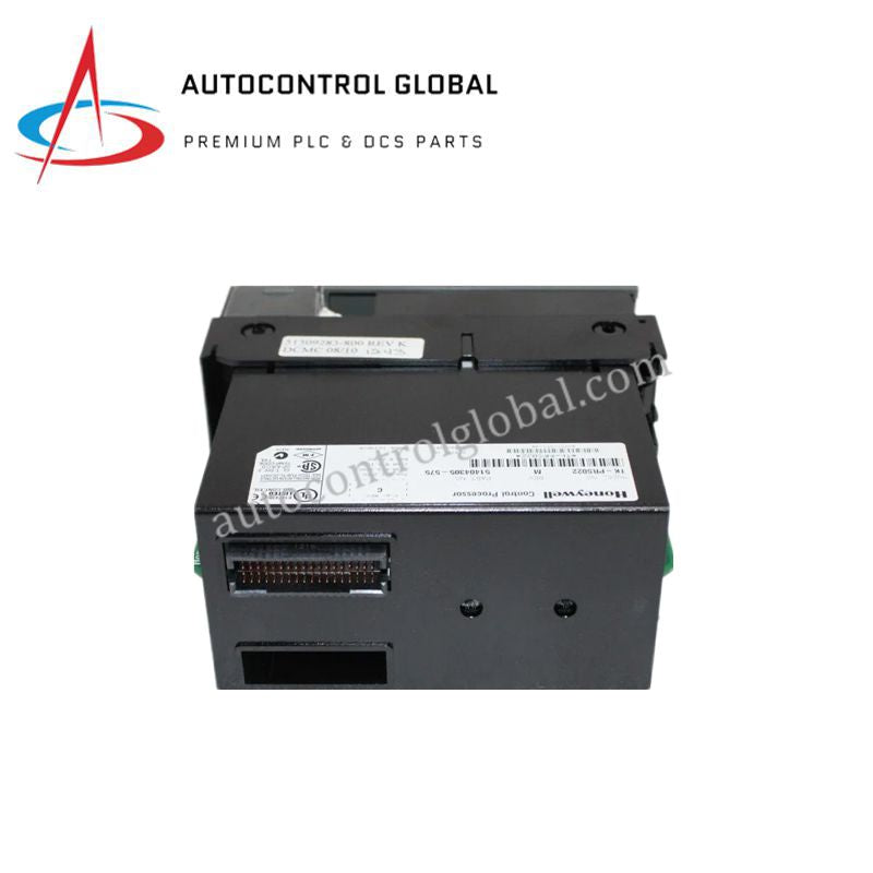


TK-PRS022 Honeywell Serial Communication Assembly
Manufacturer: Honeywell
-
Part Number: TK-PRS022 51404305-575
Condition:New with Original Package
Product Type: Communication Modules
-
Country of Origin: USA
Payment:T/T, Western Union
Shipping port: Xiamen
Warranty: 12 months
Honeywell TK-PRS022 PCM C200E Assembly Module
The Honeywell TK-PRS022, also cataloged as the 51404305-575 PCM C200E Assembly Module, operates as a dedicated hardware component for Modbus RTU communication within Honeywell C200E control systems. The module executes physical layer serial data mapping to interface external field networks directly with the central distributed control processor register architecture.
Hardware Specifications
| Parameter | Specification |
|---|---|
| Model | TK-PRS022 (Part Number: 51404305-575) |
| Brand | Honeywell |
| Origin | USA |
| Weight | 1.2 kg |
| Dimensions | 100 mm x 50 mm x 30 mm |
| Operating Temp | -20 to +60 deg C |
| Power Consumption | 24 VDC (nominal) |
| Communication Protocol | Modbus RTU |
| Storage Temperature | -40 to +85 deg C |
| Certifications | CE, TUV, UL508, CSA |
Channel-to-Channel Isolation Parameters
The hardware assembly implements discrete channel-to-channel isolation circuits to prevent external electrical path faults from entering the shared backplane. These electrical isolation boundaries isolate the Modbus RTU serial line loops from the core system power rails. By decoupling field loops, the module prevents high common-mode voltages and electrical surge coupling from interrupting continuous data transmission sequences.
Frequently Asked Questions
Q: How does the module handle backplane power distribution constraints?
A: The module operates from a nominal 24 VDC system rail. Engineers must account for the continuous internal current draw during active serial polls to avoid over-allocating the localized rack chassis power supply threshold.
Q: What are the limits regarding hot-swap module replacement during active network cycles?
A: This assembly supports hot-swap replacement rules governed by the C200E chassis specifications. Removal during an active data cycle will instantly suspend the Modbus RTU interface loop and generate a communication time-out fault token in the master controller.
Field Installation Guidelines
- Chassis Alignment and Insertion: Insert the module into the designated slot of the C200E chassis using the integrated alignment guides. Push the card completely into the rear interface until the mechanical locking clips seat firmly into position to maintain steady backplane terminal connection pressure.
- Shielding and Serial Ground Execution: Connect all Modbus RTU serial cable shields to a single, dedicated instrument ground bar within the control enclosure. Route all low-voltage communication loops away from heavy AC power cables and high-frequency inverter drives to eliminate inductive noise patterns.
- Terminal Block Wiring: Strip serial communication conductors to the specified lengths before tightening the connector screws. Check terminal connections to verify that no loose wire strands span across adjacent channels, preserving the rated loop isolation margins.