


TK-SMPC01 Honeywell Experion PKS Datasheet & Technical Manual
Manufacturer: Honeywell
-
Part Number: TK-SMPC01
Condition:New with Original Package
Product Type: Power Supply Units
-
Country of Origin: USA
Payment:T/T, Western Union
Shipping port: Xiamen
Warranty: 12 months
Honeywell TK-SMPC01 Experion PKS Series
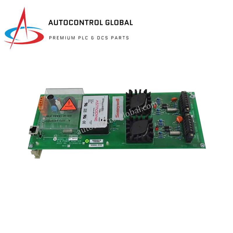
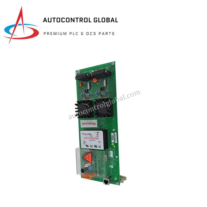
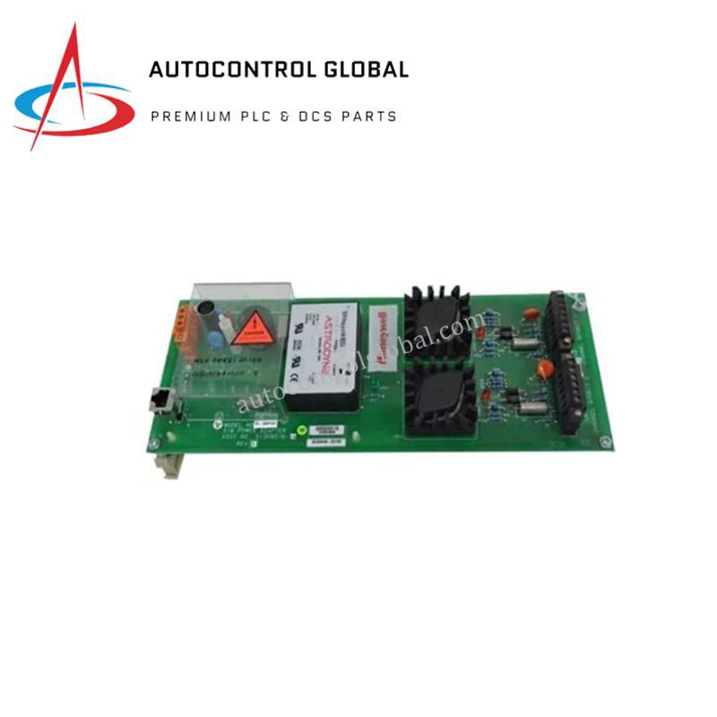
The Honeywell TK-SMPC01, also cataloged as the Honeywell 51309516-175 Power Adapter SIM PCB Circuit Board, operates as a dedicated hardware component for stable and regulated DC power delivery within Experion PKS, TPS, and TDC3000 platform networks.
Hardware Specifications
| Parameter | Specification |
|---|---|
| Model | TK-SMPC01 (51309516-175) |
| Brand | Honeywell |
| Origin | USA |
| Weight | 0.635 kg |
| Dimensions | 240 mm x 130 mm x 200 mm |
| Operating Temp | Manufacturer standard industrial rating |
| Power Consumption | Power translation component (85-265 VAC Input) |
| Product Type | Power Adapter SIM PCB Circuit Board |
| System Compatibility | Experion PKS, TPS, TDC3000 |
| Input Voltage Range | 85-265 VAC |
| Certifications | CE, COO |
Process Control and DCS Instrumentation Power Conditioning
The circuit board regulates incoming line power down to standard internal DC potentials required by adjacent logic modules and data rails. It utilizes dedicated channel-to-channel isolation filtering networks to suppress electromagnetic interference before it can disrupt sensitive 4-20 mA HART loop protocol signals on the shared bus. High-efficiency internal switching loops deliver clean current output profiles while maintaining localized power factor corrections. Additionally, transient voltage clamp circuits are integrated alongside the system backplane to insulate the primary microprocessor arrays from common-mode voltage spikes and line frequency anomalies.
Frequently Asked Questions
Q: How does this power adapter handle redundant power configurations within the chassis?
A: The board features integrated diode-ORing circuitry that permits parallel connection with a secondary power adapter module. If one power source drops out, the load transfers instantaneously across the backplane bus without interrupting controller uptime or introducing noise.
Q: What are the primary backplane thermal constraints when running this module at maximum 265 VAC input?
A: High-voltage inputs generate proportional internal thermal loss within the voltage regulator stage. The PCB relies on the standard cooling fan assemblies of the Experion PKS or TPS cabinet to maintain its component surface temperatures within nominal limits.
Field Installation Guidelines
- Chassis Card Cage Mechanical Guide: Align the edges of the SIM PCB with the designated vertical tracks in the carrier chassis. Gently press the assembly inward until the multi-pin terminal connector mates securely with the host motherboard bus.
- AC Input Terminal Safety: Strip back variable input supply lines (85-265 VAC) precisely to the factory-recommended depth. Screw the conductors down firmly into the terminal block to prevent high-contact resistance from generating heat.
- Cabinet Shield Grounding: Verify the structural mounting screws establish a clean, low-impedance metal-to-metal connection with the cabinet sub-plate. This bond is essential for routing high-frequency filter noise away from the logic circuits to earth ground.